As I went over, I decided to make an after market rad support. The old one was obtrusive, bent, and would have taken longer to make look nice than simply replacing it.
With the elongated caster rods in place, it was time to work out just what the new final resting place of the radiator was. Initially, the rad support blocked relocating a radiator (of any use able size) further forward in the chassis. With that gone, it was a matter of trimming any other non-structural metalwork that prevented the radiator from being further tucked.
I made up a mock up radiator out of some MDF to serve as a guide and started trimming out the back of the headlight buckets.
This was during the whittling process and as such very rough - lots and lots of very small cuts to make sure I don't gut too much. It was plenty cleaned up later on.
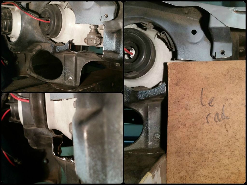
With width dictated by the frame rails, after removing some of the headlight bucket the next component to foul was one of the high beam adjustment linkages. I needed to pull apart my headlights at some point anyway (made the mistake of welding near them and buggered the glass) so I did it sooner rather than later to see if modifying the linkage could help my cause.
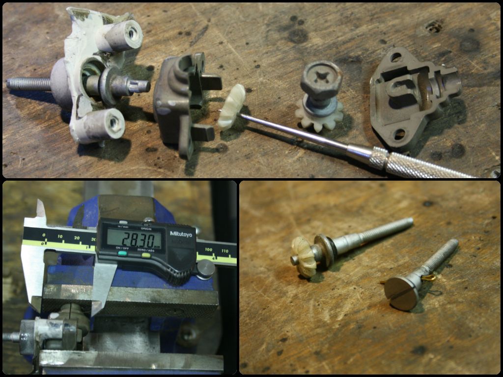
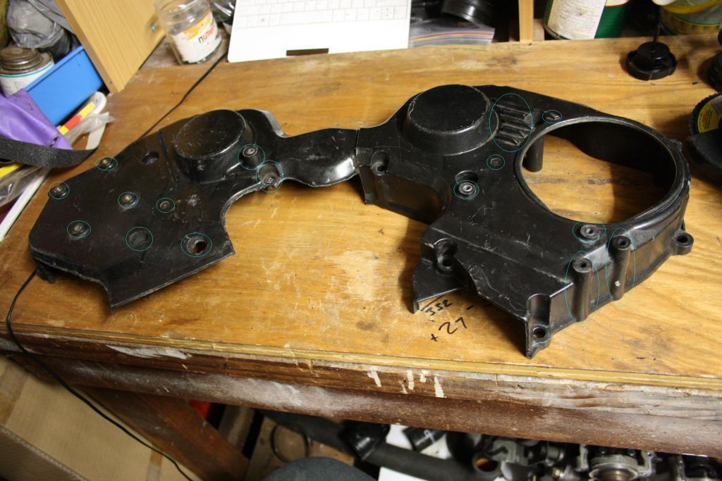
This I guess is an "exploded view" of the factory inner high beam adjustment linkage. The long bolt was initially held in place by a housing that bolts to the back of the headlight, while now it is secured with a split pin inserted through on the inside of the headlight. The bolt was then trimmed and slotted on top so I could wind it with a flat head. The factory linkage is designed to be adjusted from above, but my upper rad support is all welded up so that isn't possible anyway. This new set up is actually (in my case alone) more practical too, which is neat.
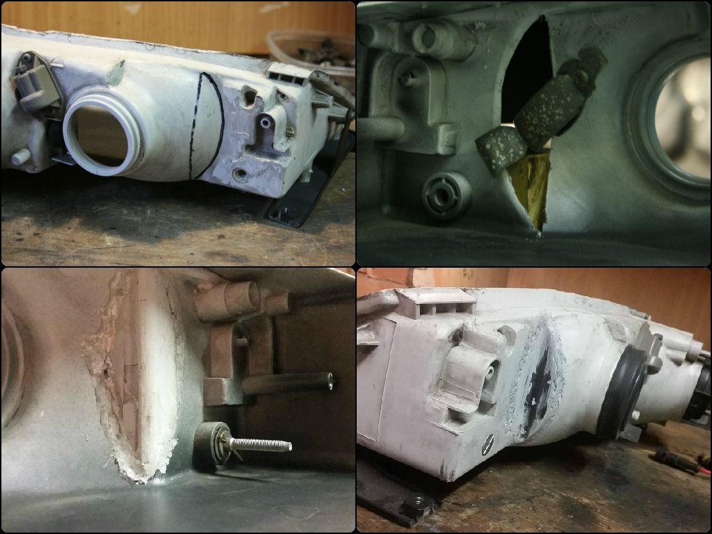
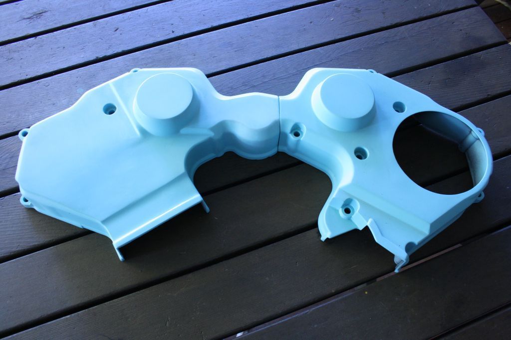
Next step after that was removing a bit of the plastic housing too. With a whole lot of measuring, I worked out that I could cut a portion out, replace it with L-section plastic and not limit the adjustment of the high beam lens in doing so - Mr. Nissan left heaps of extra room inside the housing.
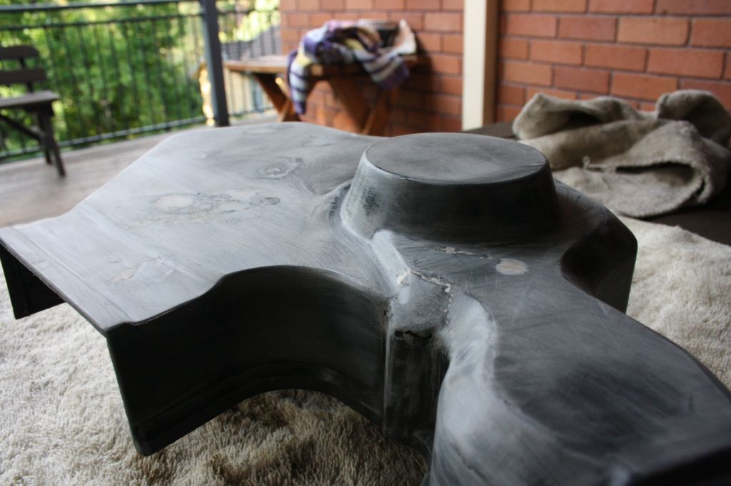
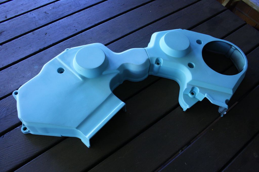
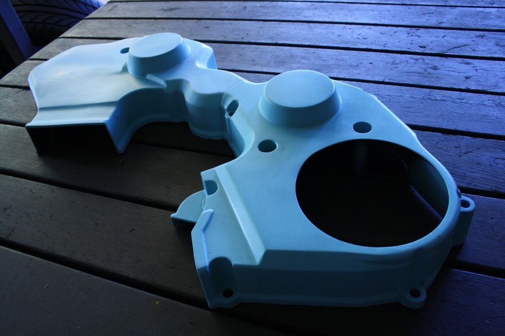
Housings were cut up, new pieces plastic welded in and the inside of the housing sealed with two part epoxy for water proofing (I'm not that gun of a plastic welder). The top right pic shows the new position of the (wooden) radiator with the now modified headlight housings. The newly added split pin is in the bottom left pic, and you can just make out the now slotted bolt head in the bottom right pic.
All in all I was able to move my rad forward a further 30mm after doing this, and the headlight functions just the same as it always did. Extreme, probably, but I'm satisfied the rad's as far out of the way as it could be within reason.
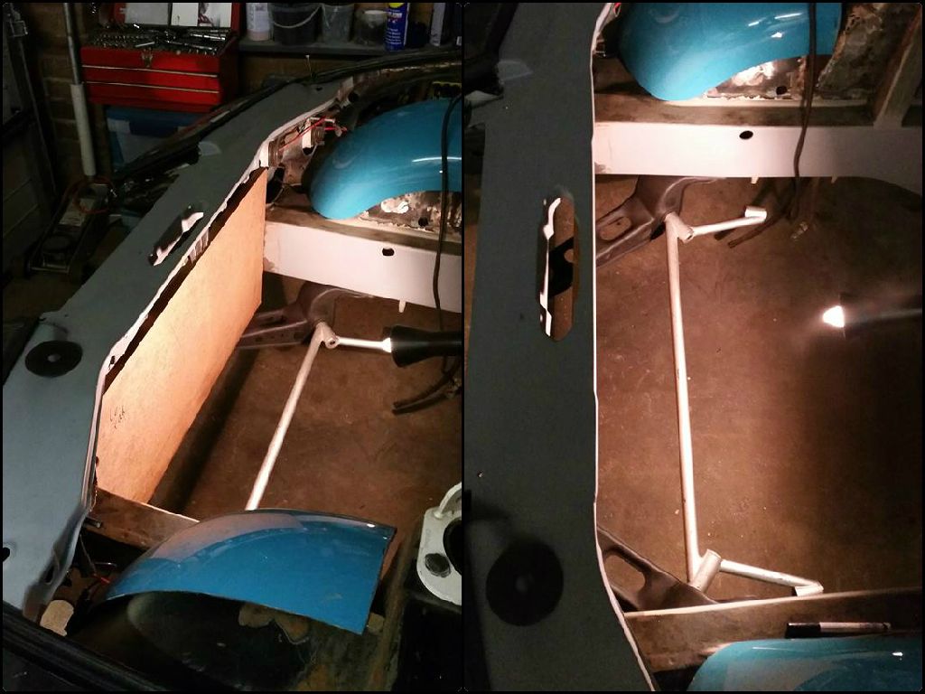
More or less totally out of sight. Pretty happy with that.
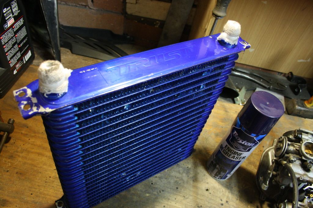
The challenge here was not just how far forward the radiator could be, but (somewhat obviously) the how big it would be too. Z32s in a warm climate like mine are notoriously hard to keep cool with electric fans, so much so that if you even mention them on the Aussie forum you'll be lynched. The reason for this is that relatively speaking, the radiator in a Z32 twin turbo is tiny. It's also almost square; at best only a single 16" fan can be bolted up to it and this plain and simple doesn't have the air pulling capabilities to compete with even stock cooling mechanical fan. The rad I'll have to make up to fit in this location has about 20% more surface area (2760 cm� vs 2200cm� stock) but being a whole lot wider, can also have two 14" fans fitted to it. The Dereale pullers I'll be picking up advertise 2100 CFM each, so combined they should make for a proper hurricane keeping the car cool.
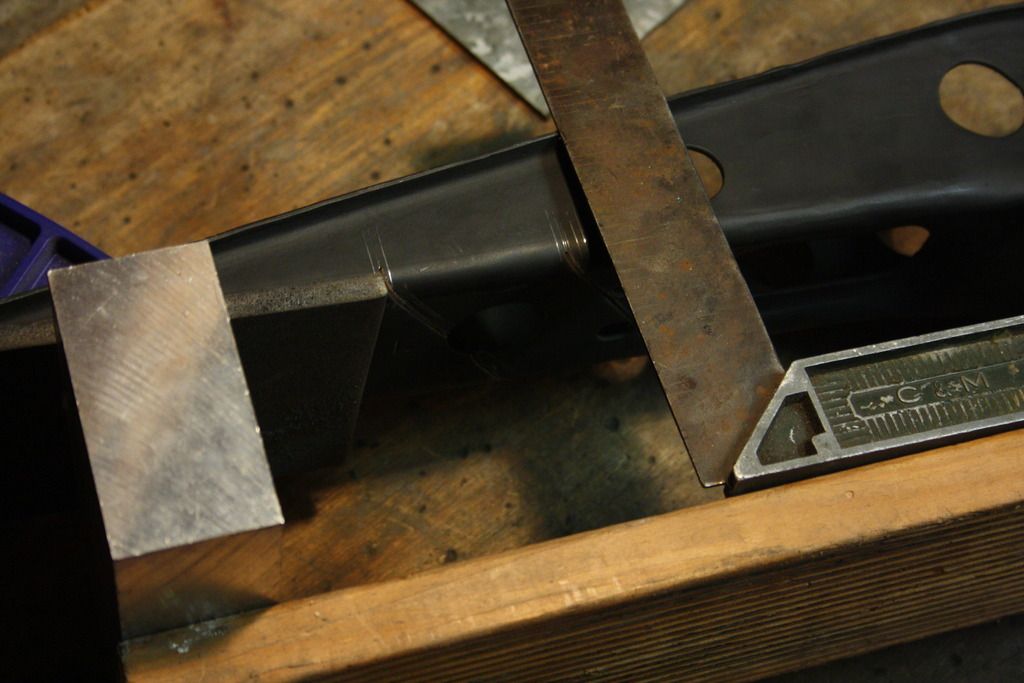
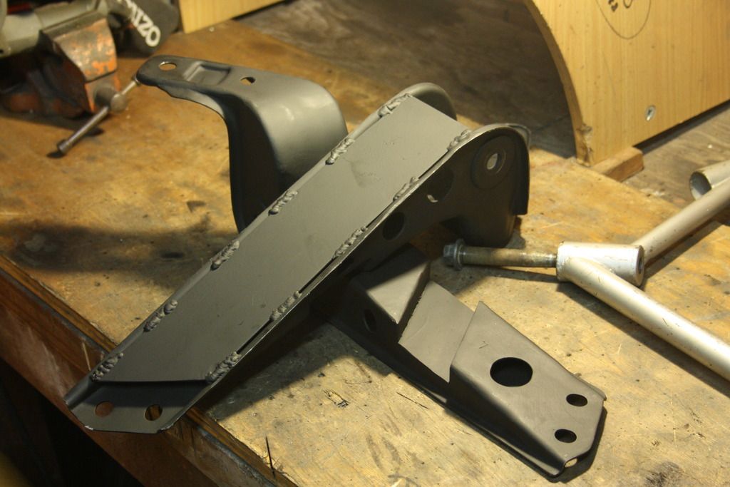
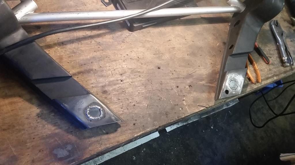
Now that the new rad location was determined I got to work further modifying the caster rod brackets to suit. They were channeled in order to make way for a little more core size and hold the radiator in its place.
The rad position was marked on them, they went back in the "jig" to ensure dead straight (relative to frame rail) markings and then got the chop. As this is obviously a structural area, I made up some 5mm plate steel U section channels to weld into the recesses. Quite sure the channels are now by far the strongest area of the whole part, haha
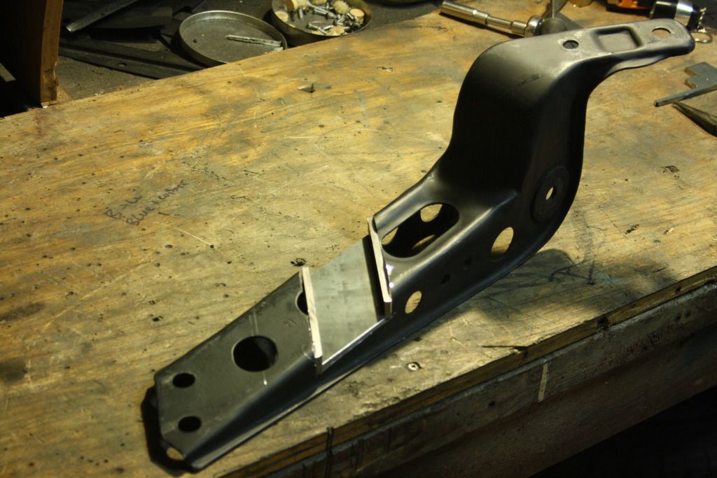
Once the channels were welded in, underside access was no longer necessary so I could finally finish the units off by gusseting the underside. This is I think is common practice among the S-chassis crowd as their brackets are considerably longer and more likely to flex than the stock Z32 ones.
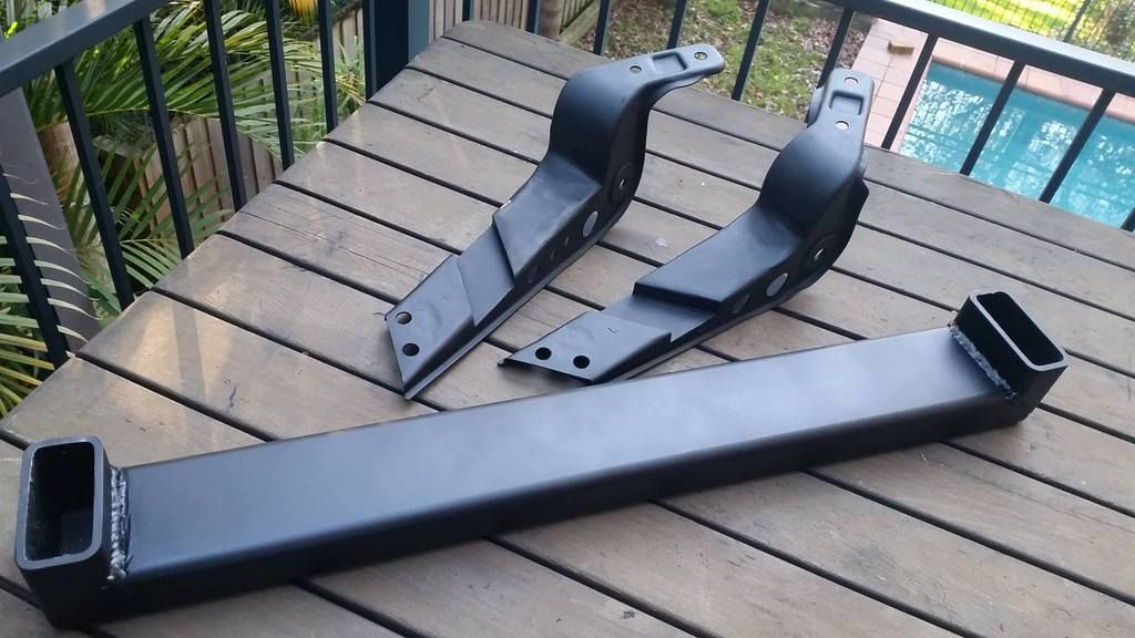
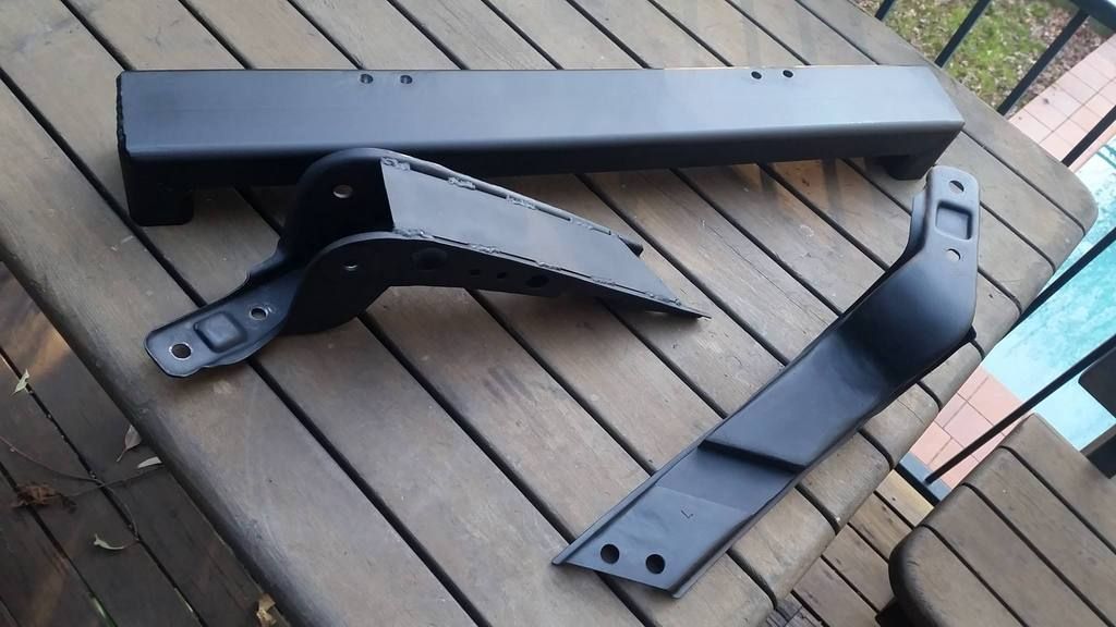
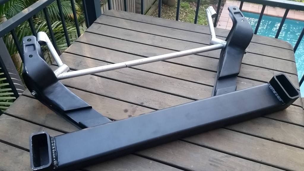
All said and done they were cleaned up and I was good to move onto the rad support itself.
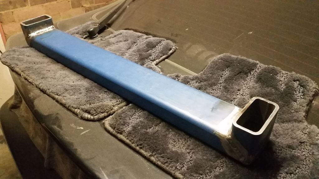
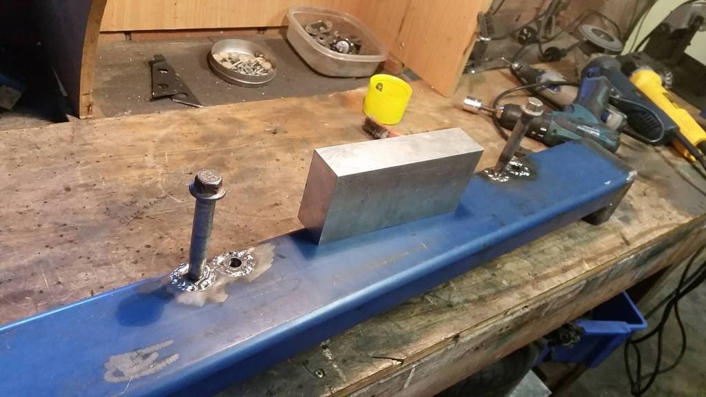
I picked up a metre or so of rectangular box section, bought a drop saw and went to it making the basic shape. This is some thick wall stuff so it's super strong, though a bit heavy.
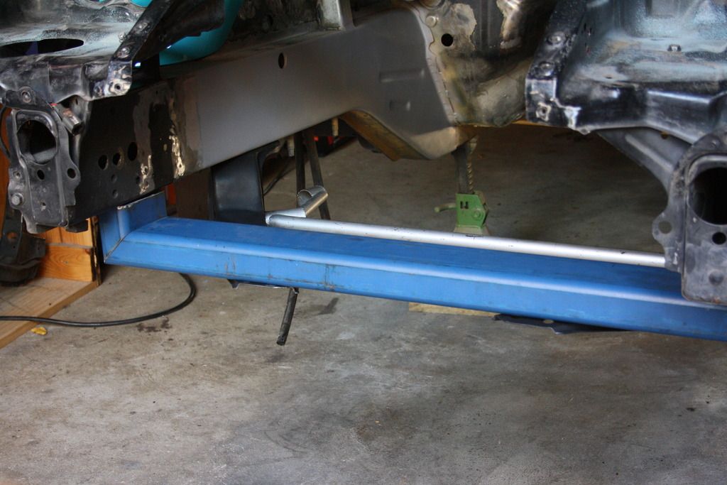
Surprise benefit here was that I could just use the jig to determine the length of the verticals without touching the car. Winning.
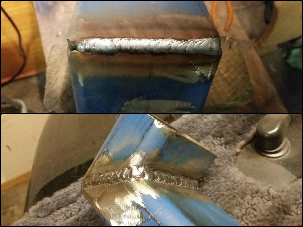
Welding welding welding. Beveled it a bit much but oh well
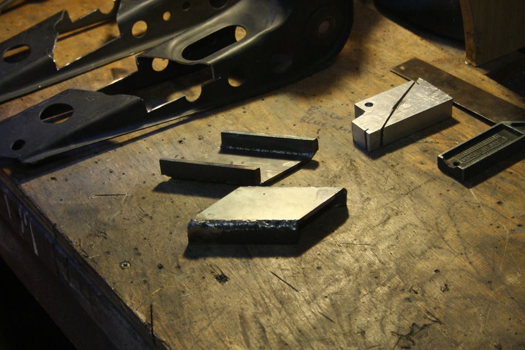
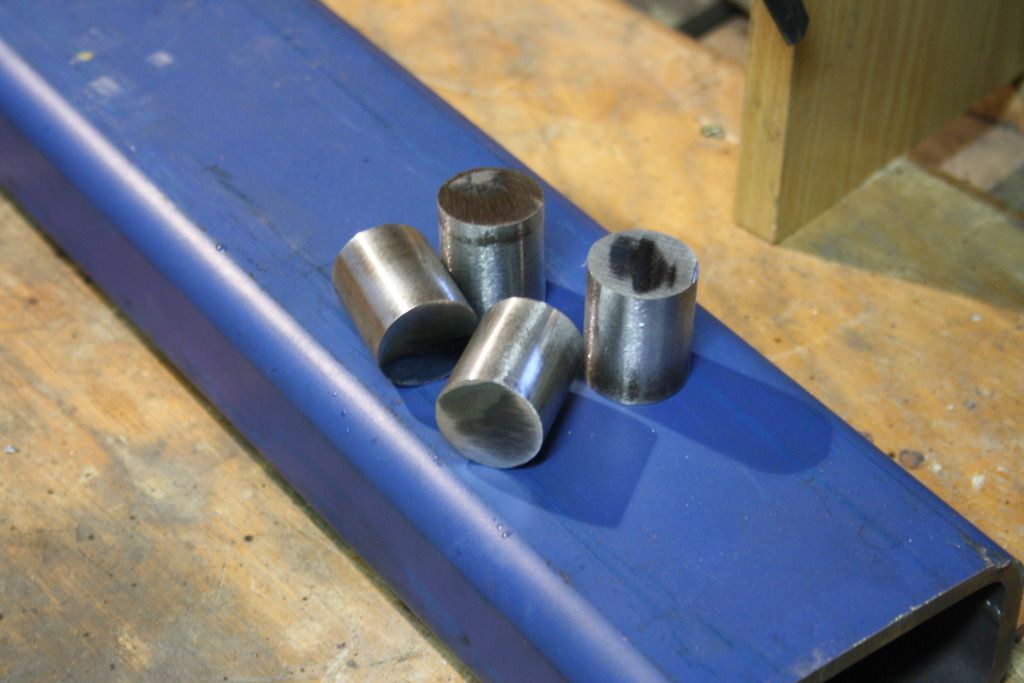
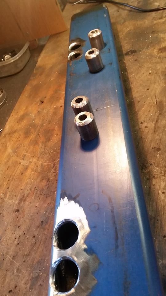
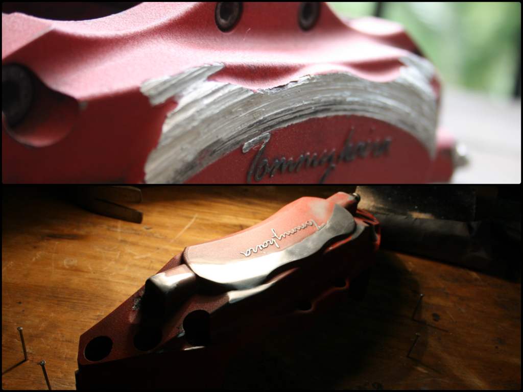
Now with the rad support made up it next had to be modified to receive the four bolts on the end of the caster rod brackets. This meant a set of captive nuts. I flexed my new drop saw muscles and cut up some scrap left over from when I made the weld-in brake master cylinder brace;
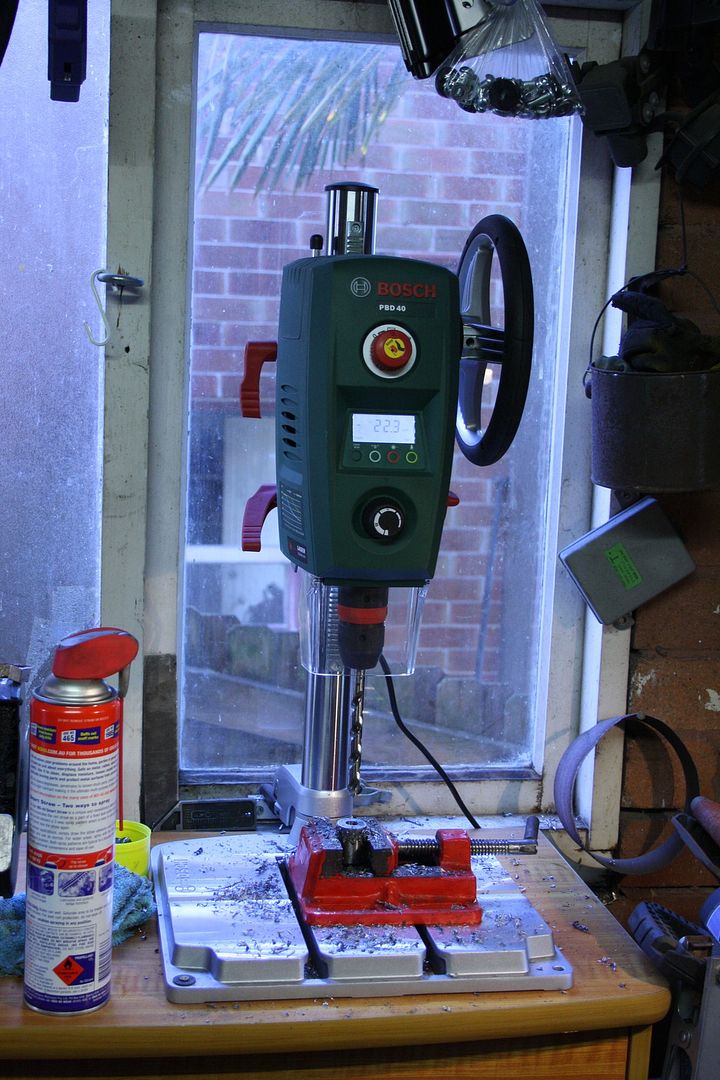
Then went out and bought myself a bitchin' drill press complete with RPM/depth readout and a laser guide that doesn't work properly.
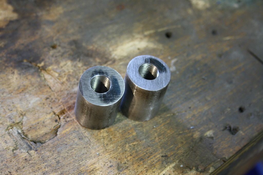
Tappin'. These bolts are exactly the same width/pitch as the brake caliper mounting bolts, which is mad because that's the only tap I actually have haha. The holes aren't centered very well which is a shame, but I'm learing how to do this stuff as I do it so I can forgive myself every once in a while...
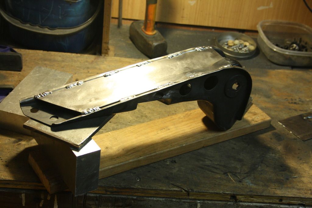
I drilled out the new support and beveled both the holes and the captive nuts so the welds could safely be ground flat after.
More welding. Chucked in some spare bolts (R32 GTR caster rod bolts if anyone needs some lol) during the welding to stop the threads warping, but I don't know if that's necessary.
Next up the last job before paint was redrilling the caster rod brackets. When the final rad support placement was concluded (that was hard, seriously) the brackets were trimmed of an inch or so of excess length (still well longer than the stock Z32 brackets), so four new holes had to be put in. Now in theory these could be painstakingly and meticulously measured out, marked and drilled and then you can kill your wife when they turn out to be bloody miles off. Anyone who's done something like this can attest to this (and their wives probably). Never work off measurements alone unless you absolutely have to. Always mark.
Once mocked up together the (non drilled) caster rod brackets covered the four holes in the rad support, leaving no gauge of where line up the drill to. To overcome this I knocked up a few of these little things. They're the same thread as the rad support, ground to have a pointed tip and slotted topside so they can be wound in and out with a small flat head.
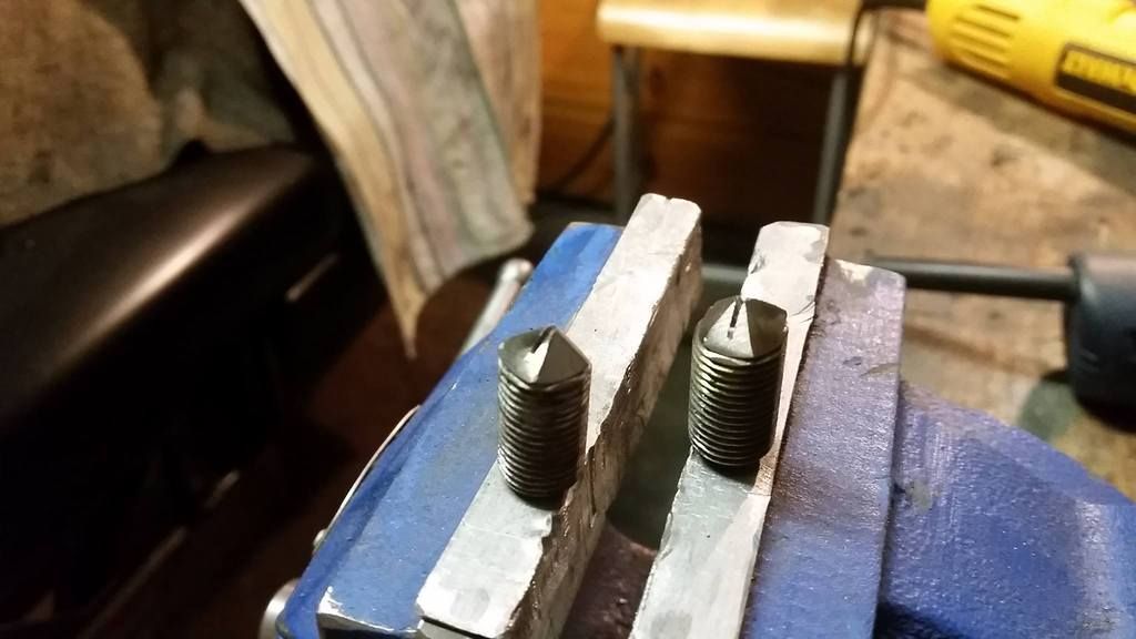
With those handy it was simply matter of threading them into the rad support with only 2mm or so of peak protruding, fitting up the rad support and caster rod bracket assemblies on the car then smacking the underside of the bracket ends with a hammer. The brackets were left with neat little imprints from the bolt tips, guiding where to drill.
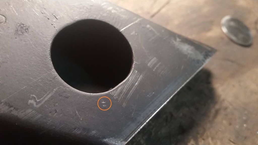
Or in my case, where you'll have to weld up a big hole because it's too close to where you need to make new smaller holes :p ahhhhhhh it's all part of the fun
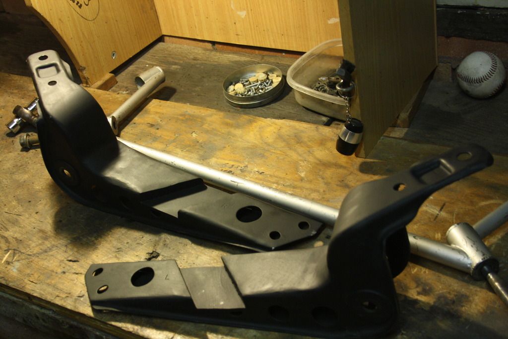
Coat of paint and they're all done and dusted.
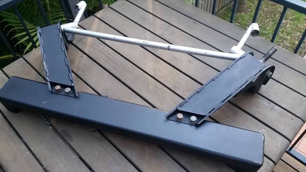
And at long last, fitted up to the car. I am not welding in the rad support just yet because my garage is a bit height restricted, and as is with the rad support out I can pretty easily skateboard a motor in for mock ups.
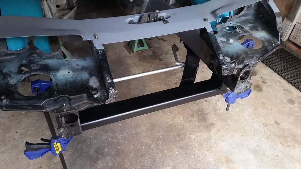
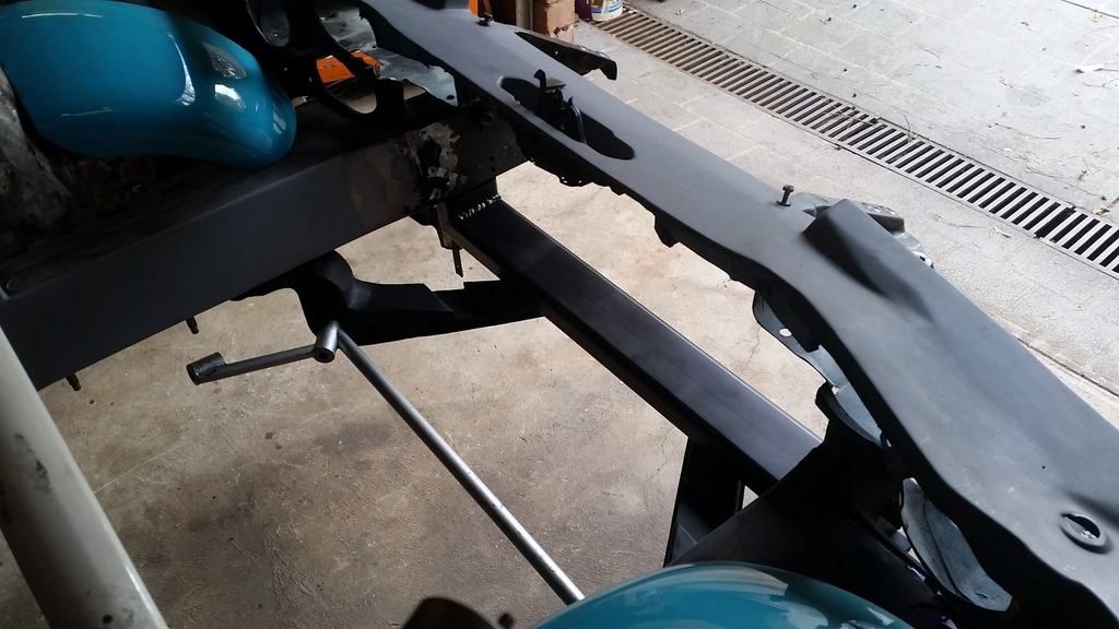
As always, more to come.
-A


Leave a comment: