If this is your first visit, be sure to
check out the FAQ by clicking the
link above. You may have to register
before you can post: click the register link above to proceed. To start viewing messages,
select the forum that you want to visit from the selection below.
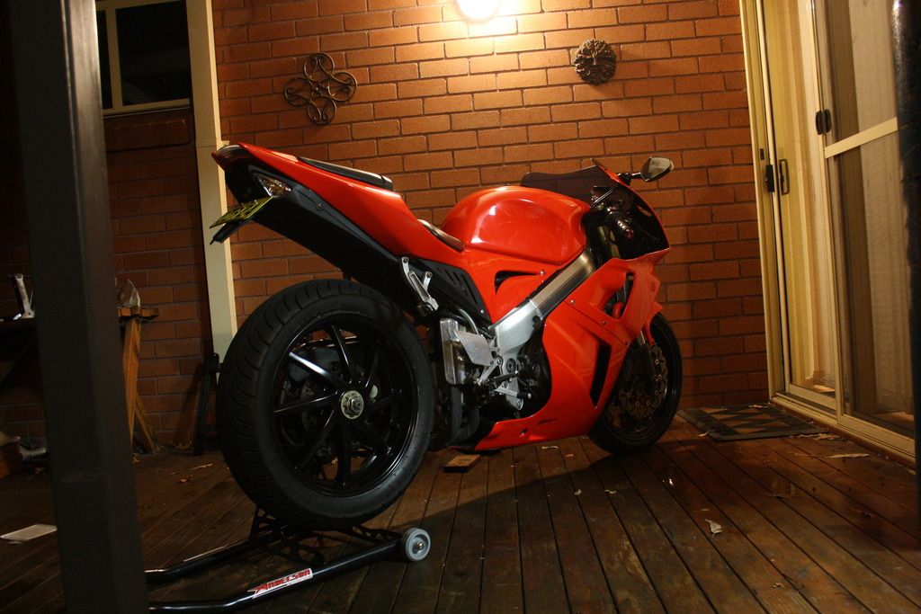
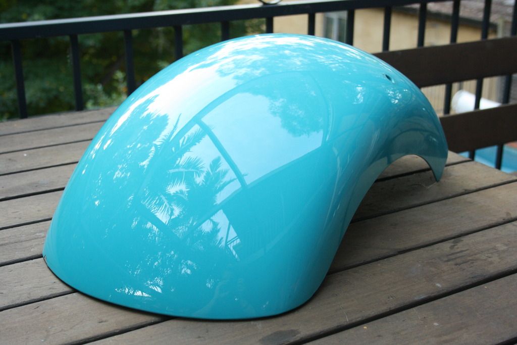
I got cleaned up by a bus on my daily (RVF400) two or so months ago and had to go to my gear shop to get a formal quote for the stuff I was wearing at the time as it was damaged in the crash. It's a pretty big place with a chopper section with a whole heap of off the shelf frame pieces and whatnot, including fenders like the one I got. They were dear as hell though ($330 AU each, about $280 USD :\) so I hawk-eye'd eBay for a while and landed this one out of Florida for just over $200 AU. I was pretty happy with that and it's a shit load easier than learning how to use an english wheel.
The bike got repainted and I got the wheels powdercoated while I was at it so it turned out to be not a bad venture at all.
Thanks man, the calipers are one of my favourite parts on the car. I don't have any Ikeya (yet...) but do have a fresh Tomei head gasket going on my motor. All the Ikeya stuff is still readily available off the shelf which sort of kills my buzz a bit hah
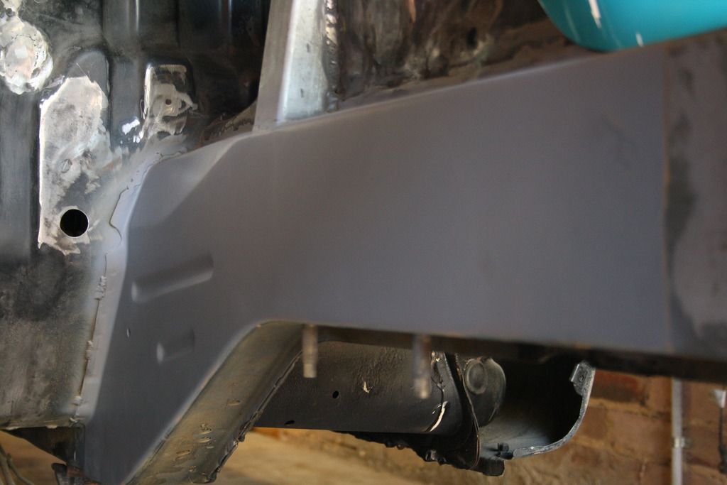
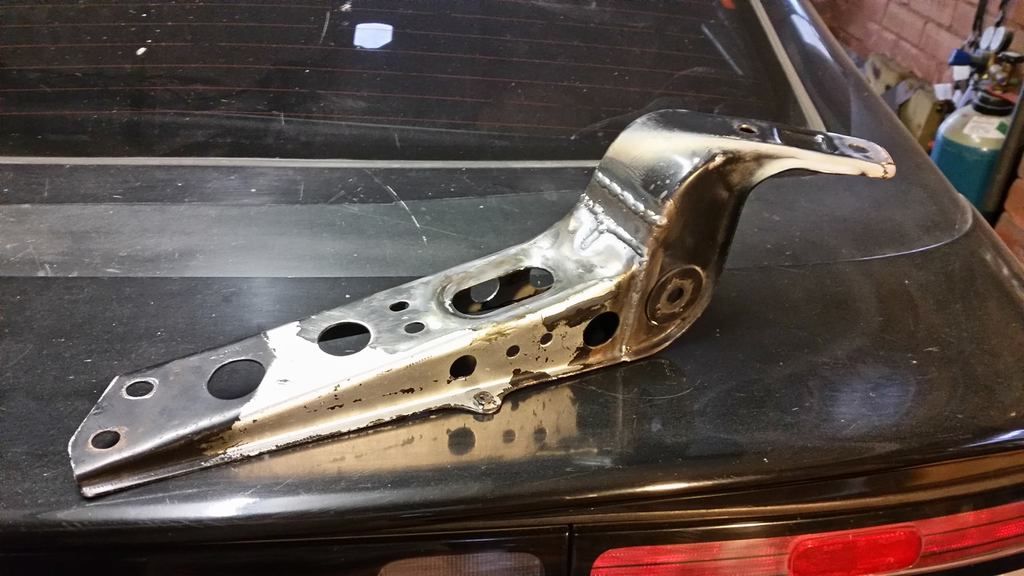
Alrighty last post and we're finally up to date. Smoothing the frame rails. I started on this ages ago (welding wise) but didn't follow it through. First bay job after the upper rad support was to be this.
All holes were welded up bar one at the rear passenger side that holds a brake line, and another at the front of the driver's side that I cut to run the power steering feed line through.
Since the rails are more or less flat out of the factory, a few skim coats of filler followed with long hits with an orbital sander were all that was necessary.
Next up was making space for the new cooling system. After a serious amount of measuring, research and deliberation I worked out a complete set up that will fit my goals of neat, efficient and tucked away out of sight. I initially thoroughly looked into and mapped out a v-mounted system. Unfortunately, as much as I love them to death I just can't bring myself to take the gamble of making one without knowing if it'll function effectively with my front end and body styling. I'm not willing to change to a reverse vented hood to allow the intercooler to vent through, and as reasonably confident as I am that the system can be made effective without that (and one or two other things), it's not worth investing in when the alternative I measured up is a still very neatly laid out guaranteed win.
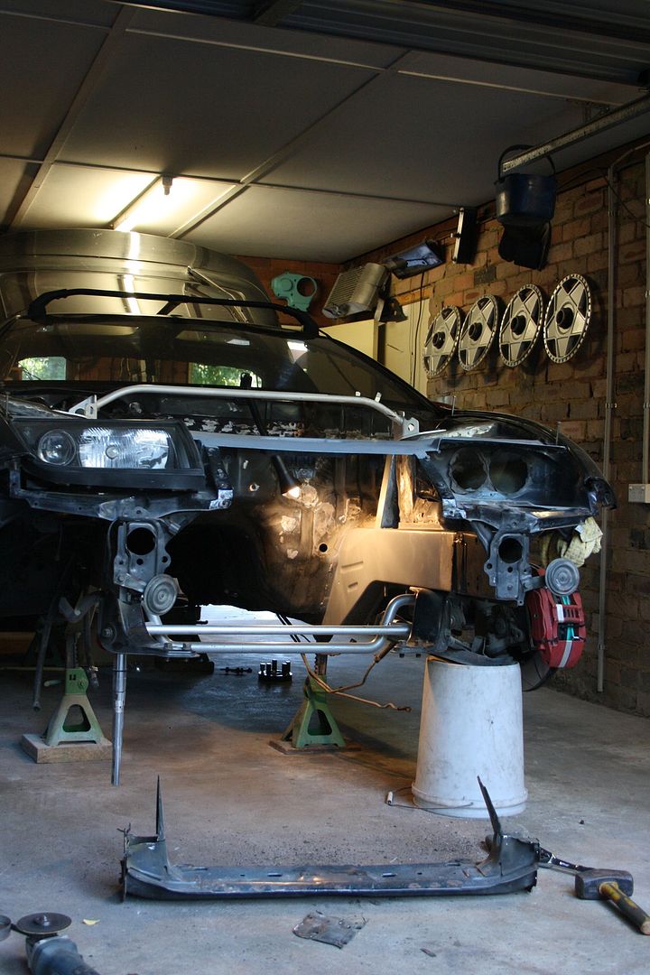
Anyway. The first step was cutting out some room for the new components.
The old support was bowed from the previous owner. It was very bulky and took up a lot of space where the new radiator is going. As a final nail in the coffin, cleaning up the factory unit was way more work than simply replacing it. So it made sense to just cut the fucker out, relocate in a new one and kill three birds with one stone.
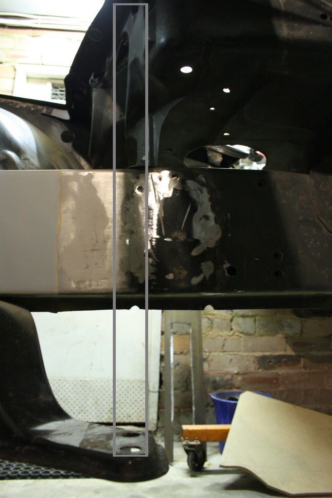
Unfortunately I couldn't just lop a section out of the rad support for more radiator clearance due to the following;
Crappy pic sorry but as you can see, the proposed new rad location just under the bonnet latch lands dead on the caster rod bracket mounting bolts. Okay, new support is getting shifted forward.
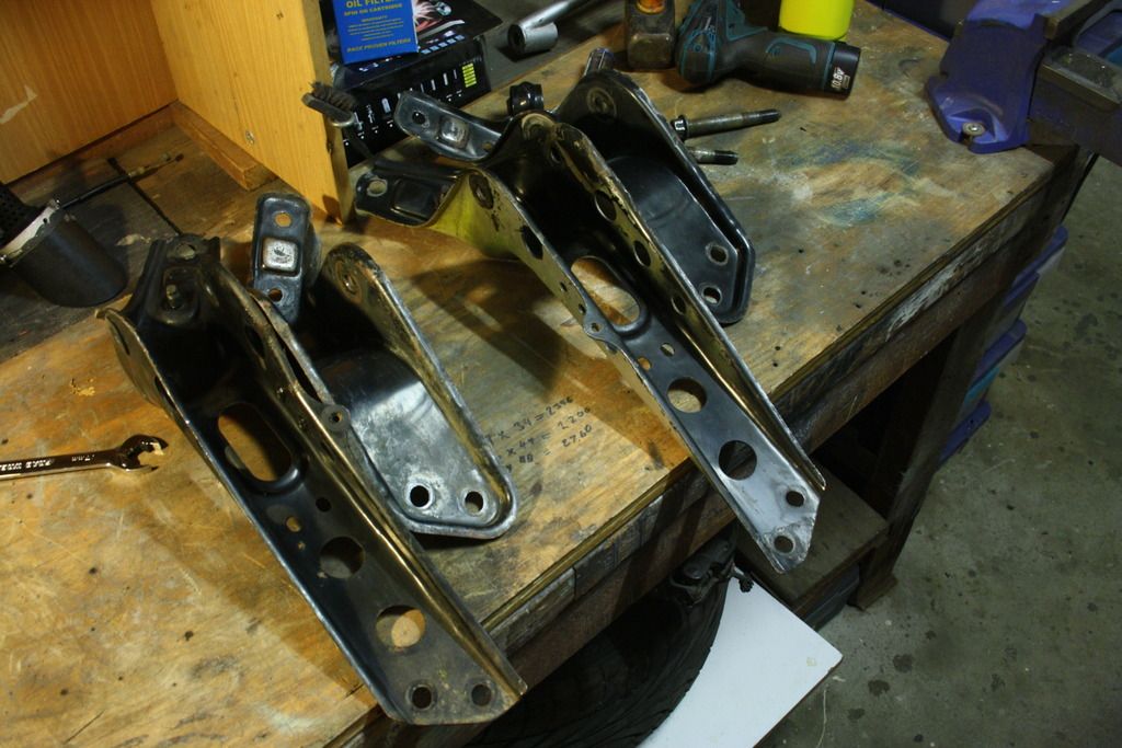
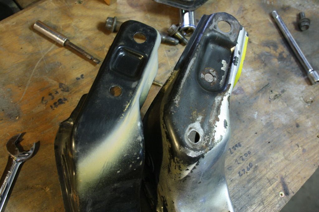
The first step for this was working out a solution for the caster rod mounting brackets. Knowing they are about twice as long I picked up some S13 units, thinking they'd bolt up. Here's a side by side;
Unfortunately, no bueno on the frame flange.
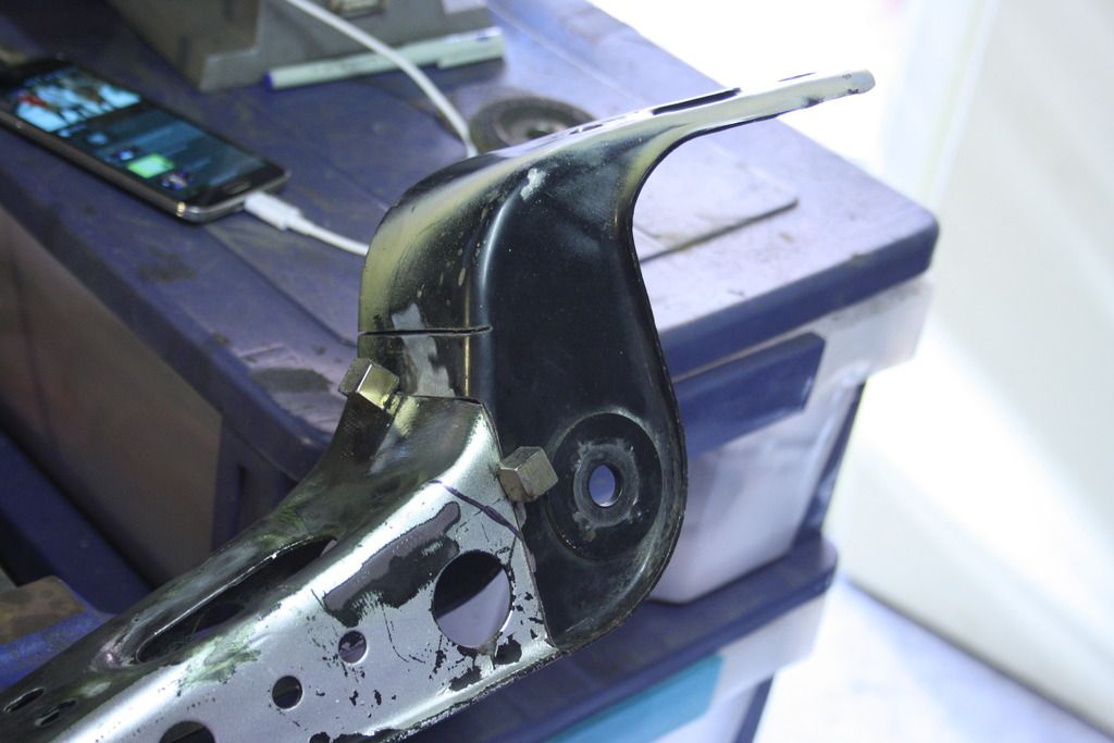
After a bit of fettling I realised not only is the bolt pattern different, but the whole design is too. Even if the Z32 pattern was adapted over the S13 units they'd still foul on the frame rail itself. Alright, time to Frankenstein.
Both brackets lopped in half and mated up, with one misguided extra cut;
There was a lesson learned in this job... the function of a jig. Keeping things straight while being welded. Ask me how I know...
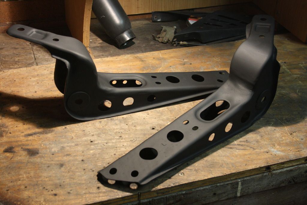
Cleaned up and temporarily rust proofed with some matte black. As these will be visible from above with the finished bay, they'll later on be powder coated along with the tension rod brace and sway bar.
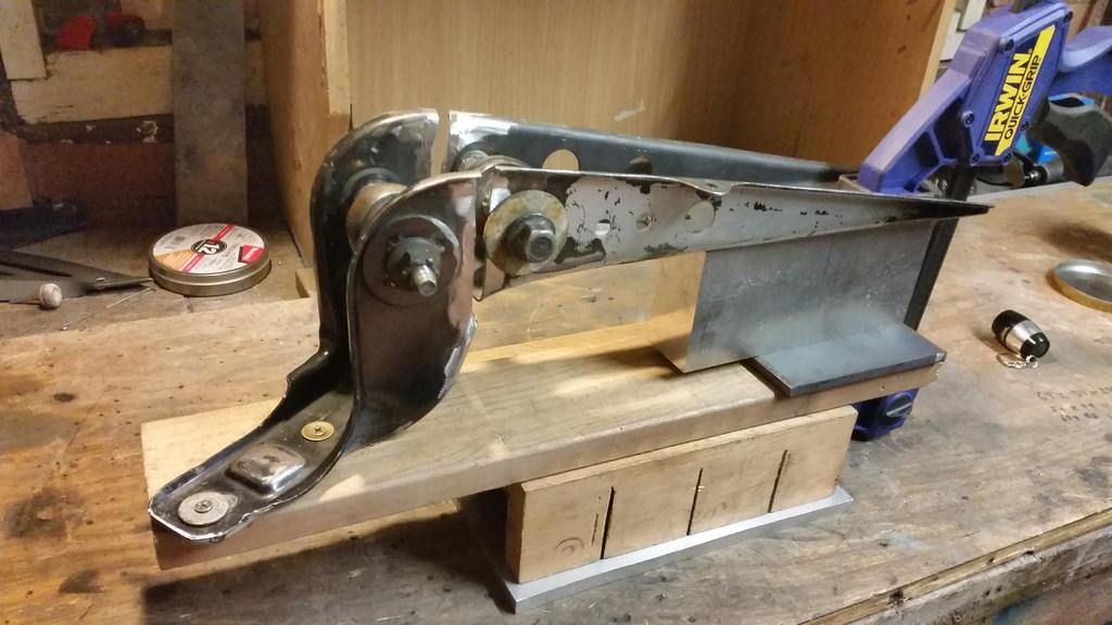
Quick shot of the gussets that'll be getting welded onto the underside for extra strength. They're not attached yet because the brackets will be modified further to house the radiator and to do so I'll need access to the underside.
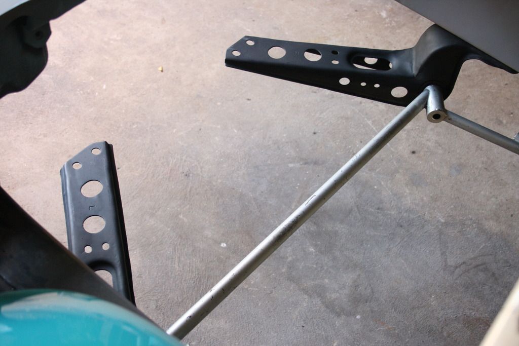
Bolted up, looking good next step will be to modify these further to receive the radiator, which will be custom built and sit on the brackets.
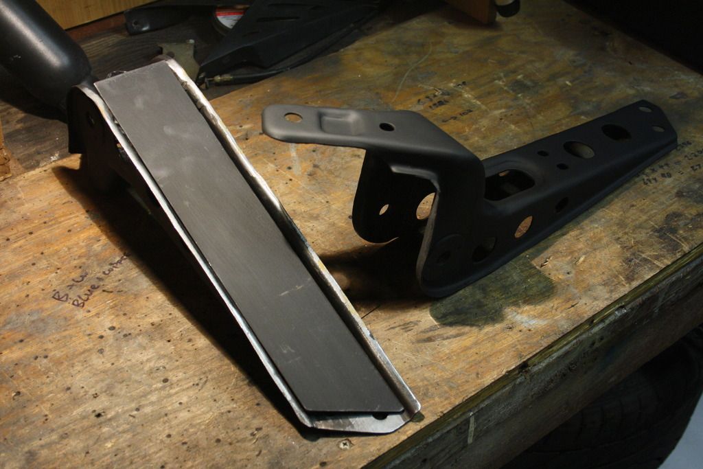
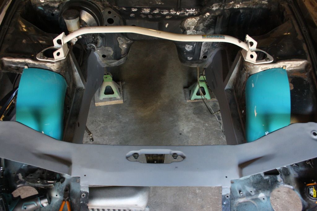
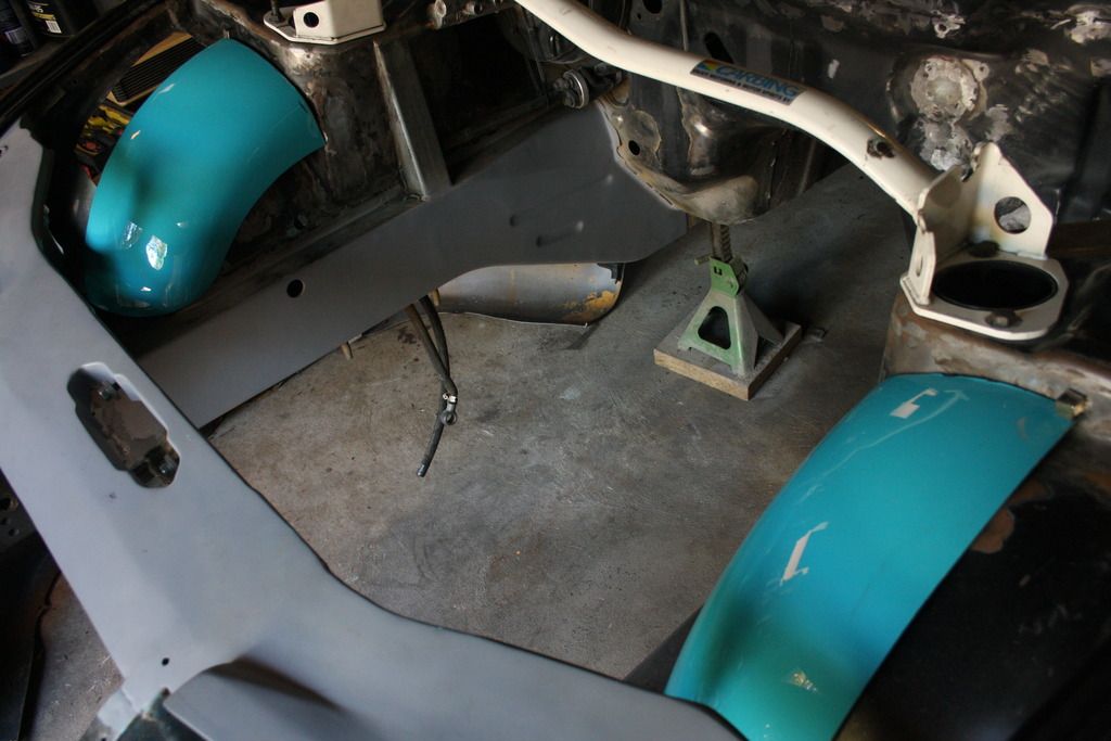
Lastly, something else came in.
It's a second hand after market fender for a cruiser with a 12" rear tyre (think this). And after being split in half right down the centre and a lot of welding it will become my front tubs.
As you can see there'll be a good amount of extension carried out on either side but it should turn out well. Next job once the caster rod brackets and new radiator support are done.
Wow thanks guys, I'm really happy to hear that. Glad I'm doing things people find remarkable, that's what I'm going for.
Ian, I have a build thread over on 3ZC. Since it's not my home turf I'm not too active on there though. Search for me under Anti.
Josh, it sounds like we've done the same thing to each other regarding our chassis' :p You reminded me that I was going to put together a post on all the random old school bits I've collected over the years; I've got a bunch more that I haven't posted about. I'll write it up.
I love oldschool Japanese parts, please show off all your cool stuff!
I've been slowly collecting Tomei and Ikeya parts for my Silvia build over the last couple years, so I know what the hunt and reward of finding the stuff is like
Wow thanks guys, I'm really happy to hear that. Glad I'm doing things people find remarkable, that's what I'm going for.
Ian, I have a build thread over on 3ZC. Since it's not my home turf I'm not too active on there though. Search for me under Anti.
Josh, it sounds like we've done the same thing to each other regarding our chassis' :p You reminded me that I was going to put together a post on all the random old school bits I've collected over the years; I've got a bunch more that I haven't posted about. I'll write it up.
I'm not big on Z32's the motor scares me, the shape didn't do much for me for years. Recently I've started to like them more and more.
Your car on the other hand, wow dude. Not only seeing the work you've put in, but also some of the parts you've bought at the same time.
Modena's perfect, Tommy Kaira and Veilside bloody wicked.
This is one of the few builds I'll be keeping tabs on, awesome work!
As a fellow Z owner/fanatic this makes me both sad that mine doesn't get the same amount of love as your vehicle does and happy that someone takes as much care time and attention to detail as you do. Mad props man. Ever thought about putting up your build on 300zxclub or twinturbo.net?
I like this "do one thing until it's finished" approach, it works well.
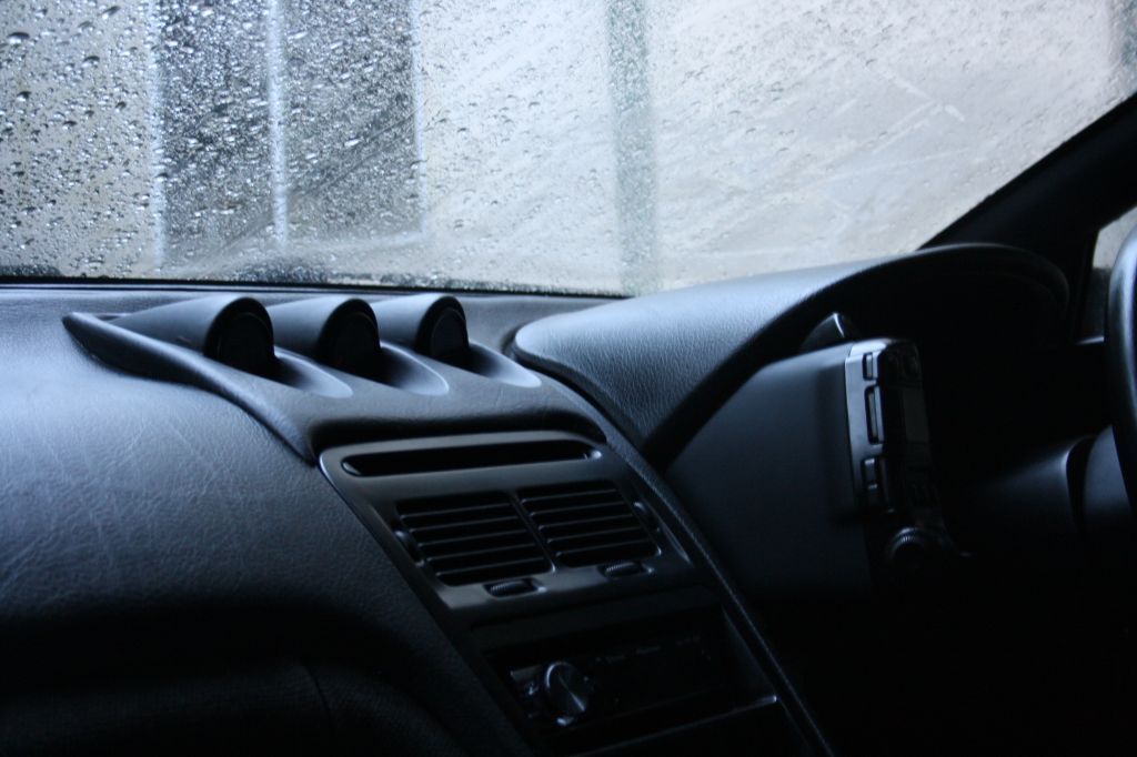
As probably most of you don't know gauge placement in these cars is a pain in the ass. There are very few places in the interior that are open for "clean" installations and there's no way I'm just going to screw holders on top of the dash. Here's my last install which honestly wasn't bad - looked slick, placement was great for visibility but two things bothered me considerably. The first was that if a globe ever blew - dash out. Secondly the simple premise of cutting a hole in the dash and tacking something on top just didn't sit well with me. Looked good in the end and the holder fit surprisingly well but it still irked me.
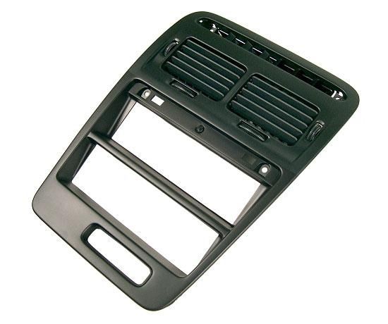
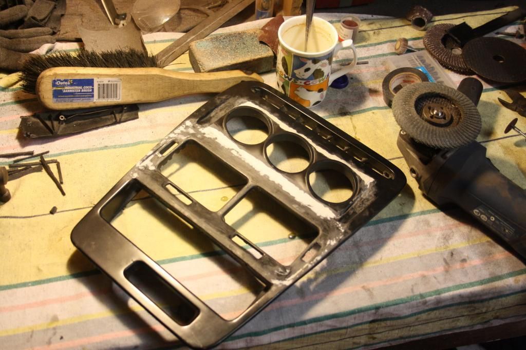
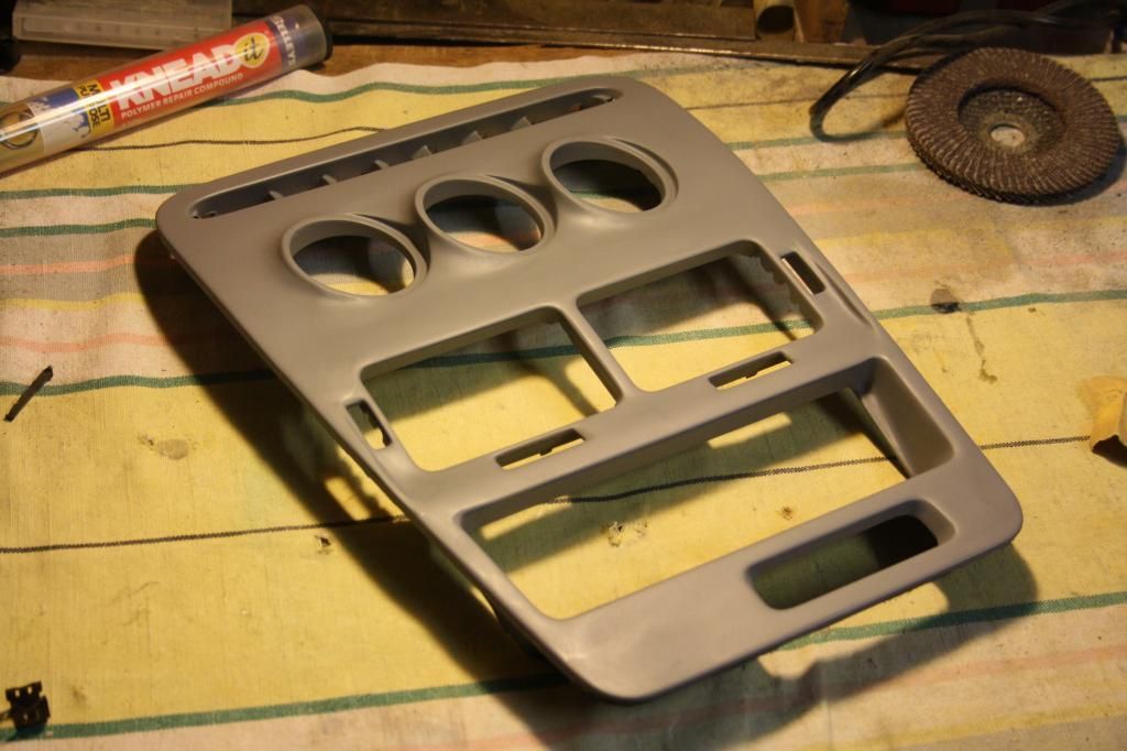
This is the stock radio surround. Most guys fit up a triple holder to one of the din slots which is fine but the viewing angle is balls. I definitely didn't want to lose that changing my set up.
When the dash came out for rewiring/seam welding I started weighing up my options. As an alternate option three gauges mounted in the din slot makes for a great use of space (who needs two din slots?) but I didn't like how low down the viewing angle is. So I put together an idea, checked/measured thrice for feasibility and... busted out the grinder.
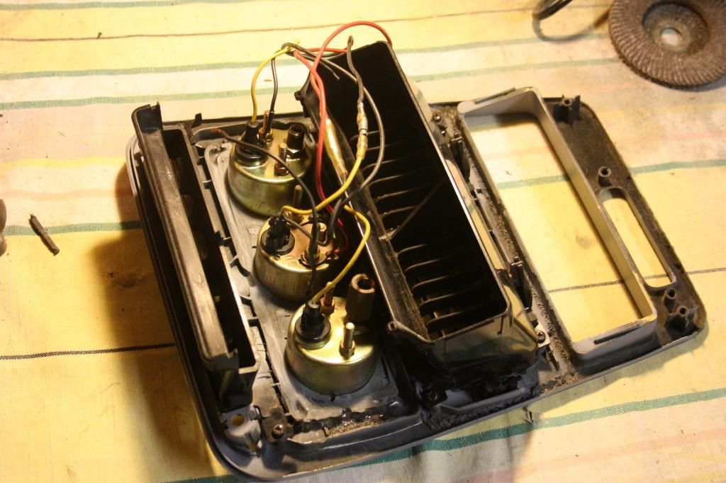
Here's the idea: relocate air con vents to upper din slot, mount gauge holder in initial place of air vents, fabricate new ducting to suit new vent placement and bob's your uncle.
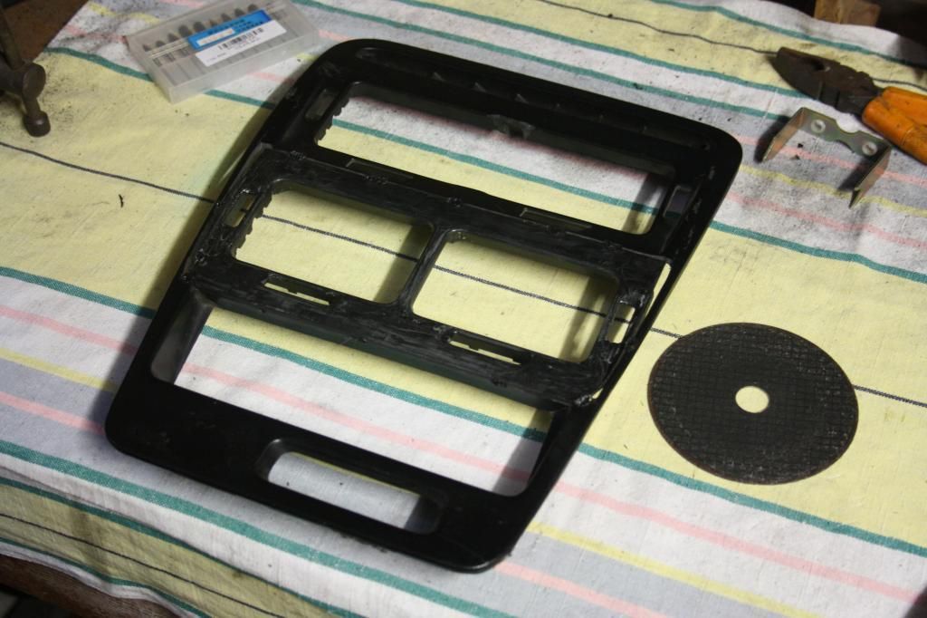
The gauge holder I selected was much smaller than the air con vents, so in order to minimise work required I cut the vents from a spare doner piece.
All plastic welded up here and ground back. Both sides of the join were welded for the most strength.
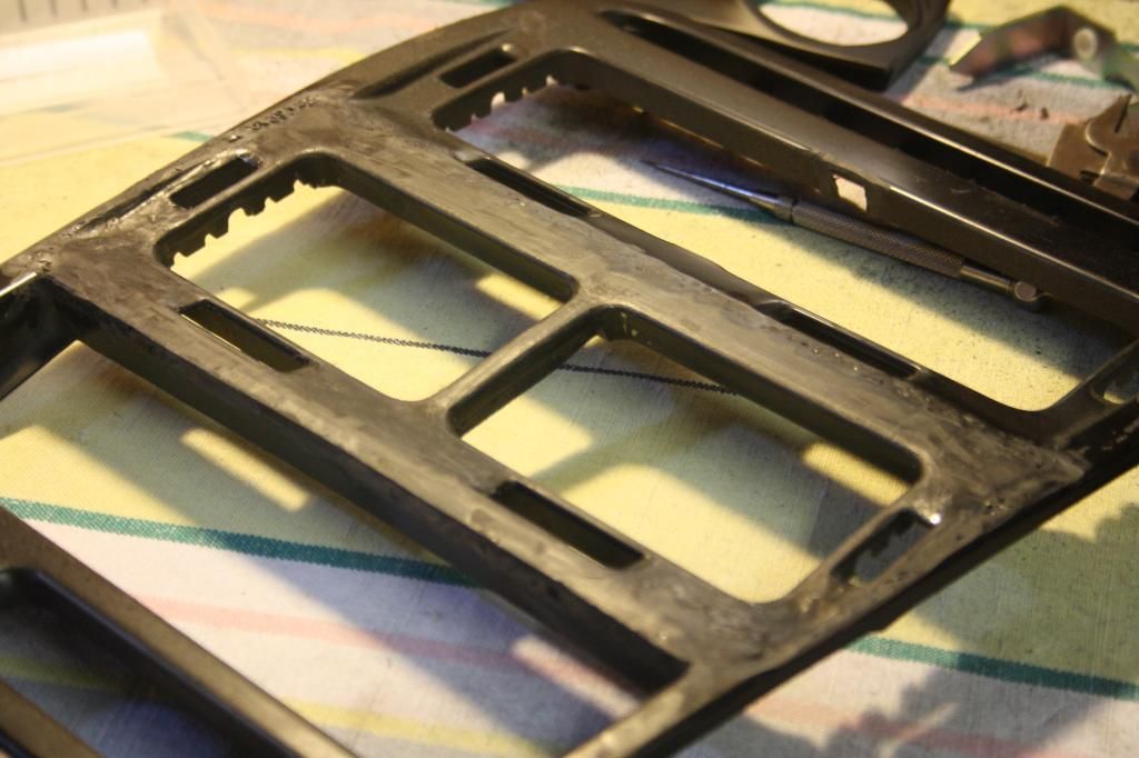
With the vent centre beam cut out and small trims to either side of the gauge holder all pieced together. The gauge holder itself is from 300 Degree and is designed specifically to fit in the lower din slot of a LHD Z32. It's odd that out of any design on the market this is the one I ended up with, but it's the exact design I was after - and it's also plastic. I was hoping to weld it in too, but no dice. I don't know which plastics weld and which don't but this one just didn't want to play ball.
While the gauge holder location was pretty much fixed, the height placement of the vents was very deliberate in order to try and avoid big open spaces on the trim piece.
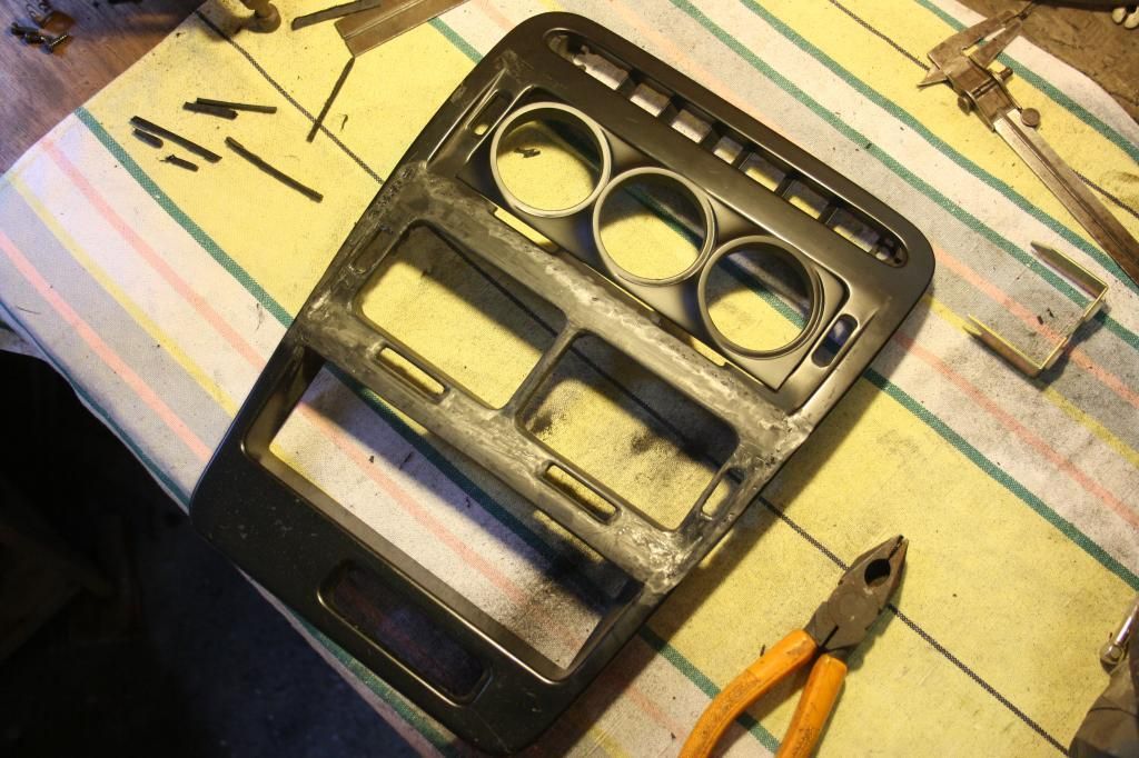
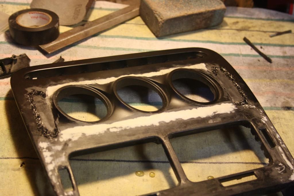
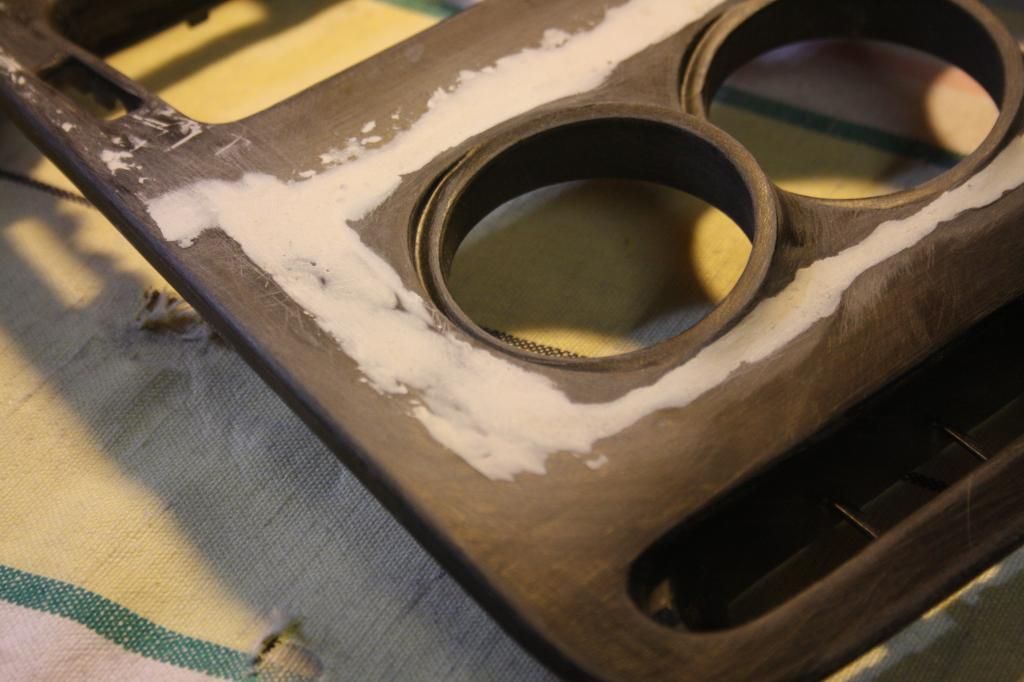
The holder was fixed in place with copious amounts of epoxy, then filler added and shaped to uniform the appearance. It's great not having to worry about moisture or (relevant) vibration when considering your filler!
Something I failed to anticipate was having to close off the dips to either side of the holder - filler strips (they looked like saxophone reeds heh) were made up and epoxy'd on before being welded on the sides. I was hoping to keep the strength of the original structure supporting the gauges in place, so I didn't cut out the plastic below.
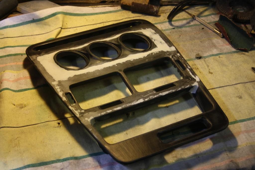
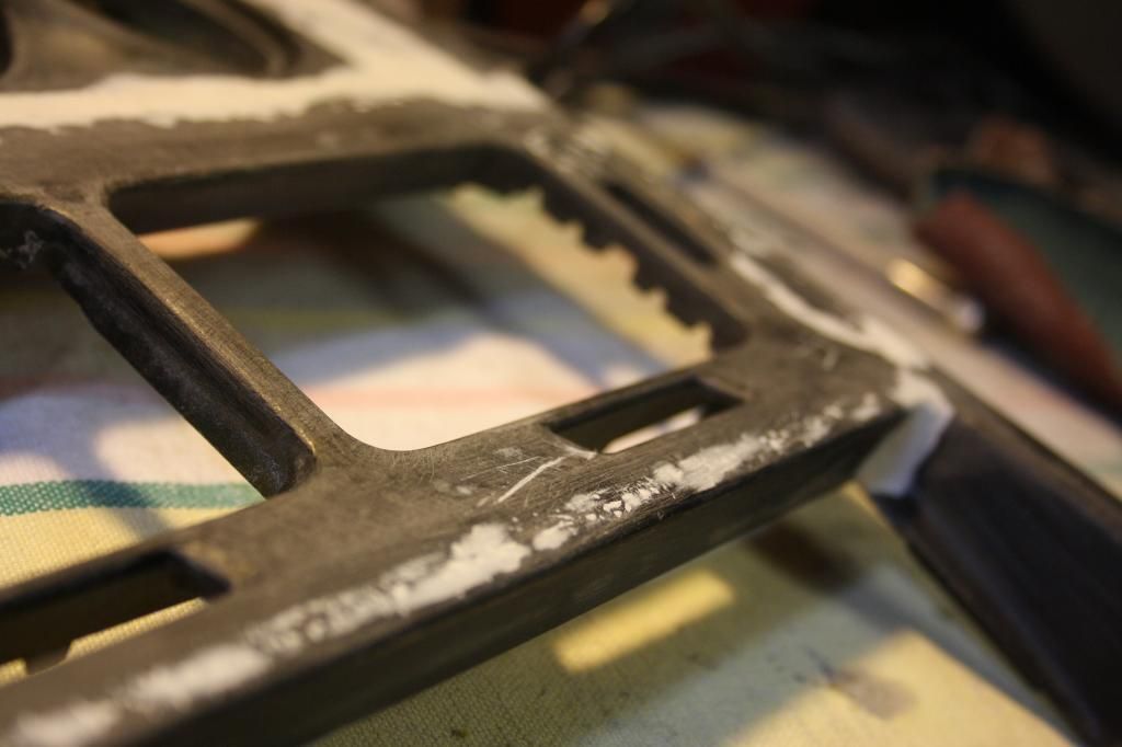
Few rounds of filler, a bunch of sanding and voila
Bloody satisfying eyeing off perfectly smooth feathering from filler to base material after a whole lot of sanding... also gives you an idea of how consistant a finish plastic welding with a regular soldering tip gets. A flat welding tip would get better results.
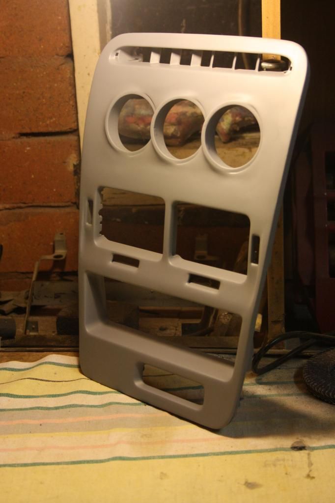
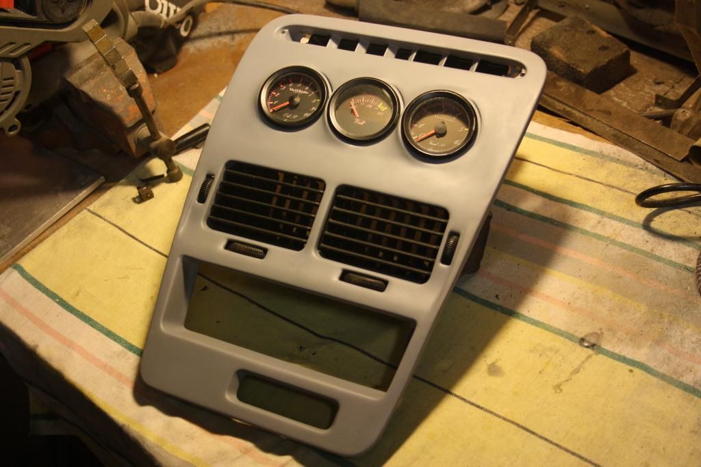
Few coats of high fill then some regular primer and here we are.
Quick shot showing the gauge angling towards the driver. Wasn't sure at this point about adding on some spacer rings to angle them towards the driver more.
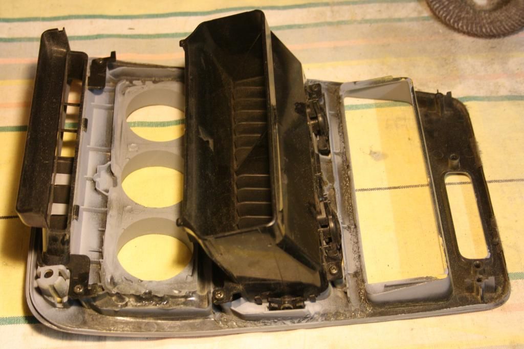
Very conveniently (and rather awesomely) the factory vent that bolts to the rear of the bezel can un-clip and split in two. It will then bolt on to each single channel in the new location separately, like it was designed that way. The ducting to these two vents will have to be made up once I have the dash back in the car.
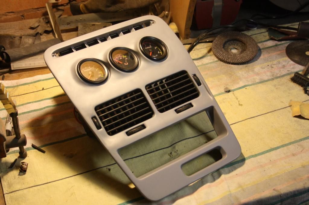
Plenty of instrument clearance.
Quick mock up with three gauges I had handy.
There was about 10-12 hours in total for this project. Not too bad and nice and leisurely all carried out while sitting down :p for the final finish I'll have it professionally painted in OEM piano black.
thanks guys, and yes I agree on the details factor. Some people get so stoked when they feel like they've ticked a box of having a mod done but you get your eyes up close and it's like... dude... we're a totally different fuckin' breed if you think that's cool.
with the welder, I just walked into a big well known chain, asked their recommendation and bought it on the spot. i'm all about second hand tools from classifieds but not with a welder; set myself up properly with something decent with warranty. it's a BOC 180, entry level as hell and unfortunately starting to restrict what I can do a bit these days. still going with it though.
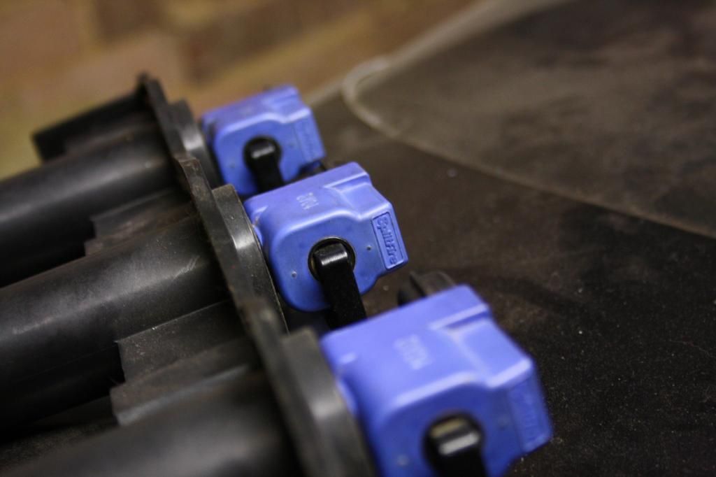
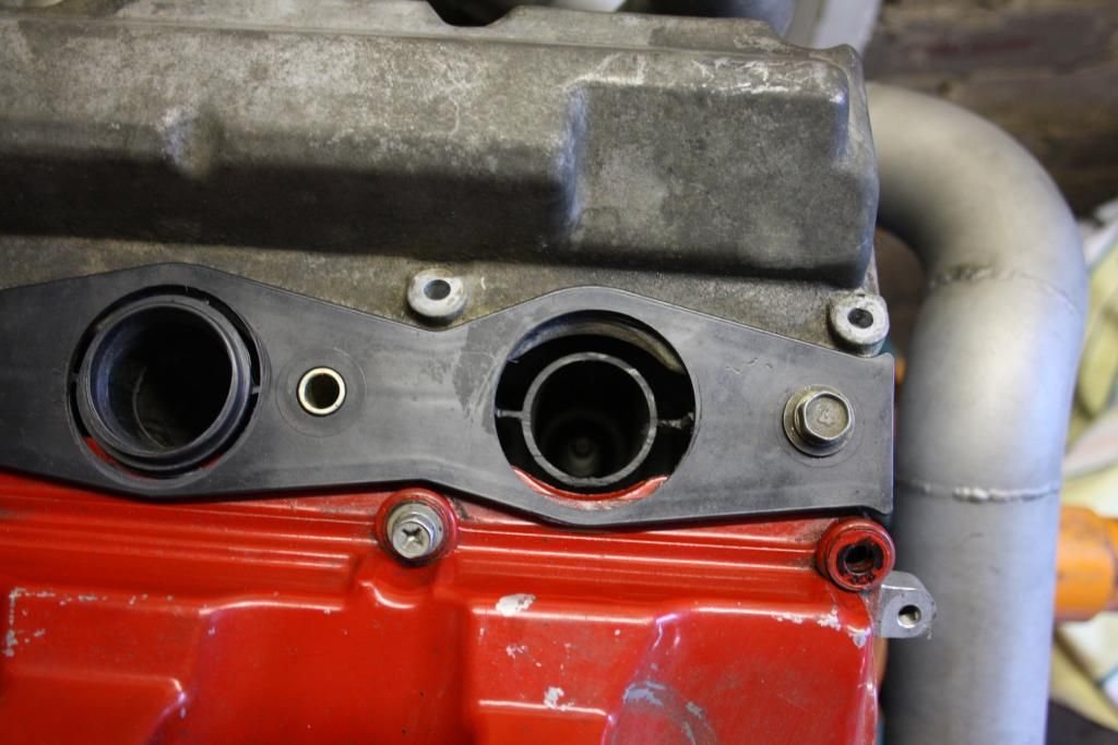
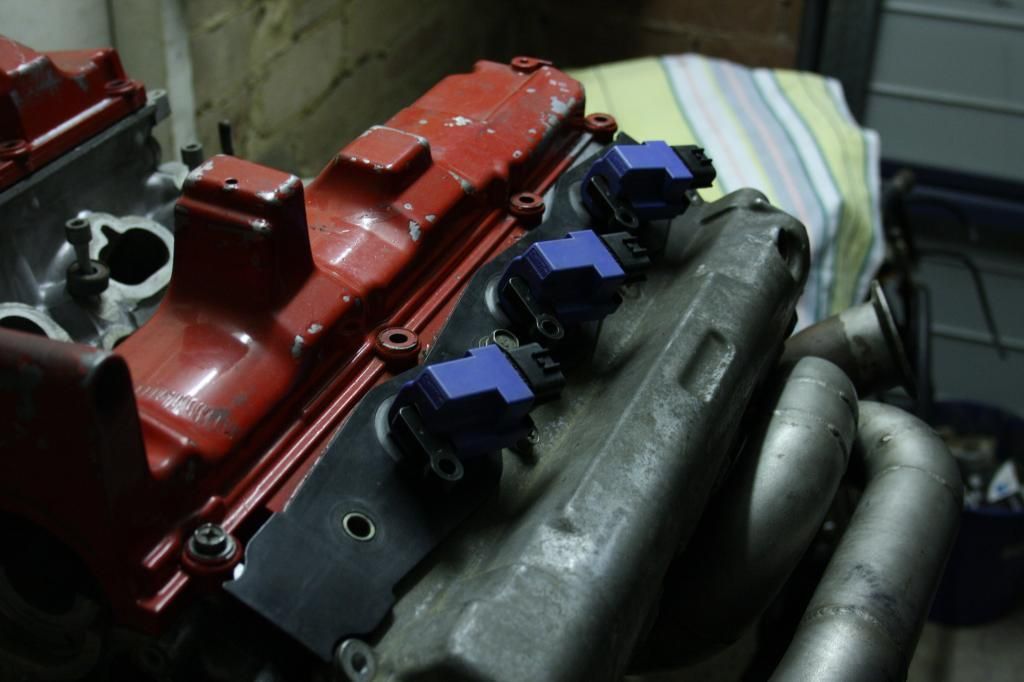
So this another project I was really keen to take on. On these cars the coil packs bolt to the inlet plenum inbetween each runner. I'm looking at going to an after market plenum, so I needed to figure out what to do with the coils. the answer was SR20 Splitfires.
Now unfortunately despite sitting so well on the factory spark plug guides, in that position the coils fail to reach the plugs. So next up was dropping the height of the coils.
The initial plan was to open up the guide, drop the coil 20mm or so, sleeve the hole with some doner piping that the coil pack skirt would seal up against the ID of and plastic weld/smooth it over topside. the guides are well sealed up for a reason - no material dropping down near the plug that could fall into the combustion chamber during a service, so it was important to maintain this seal.
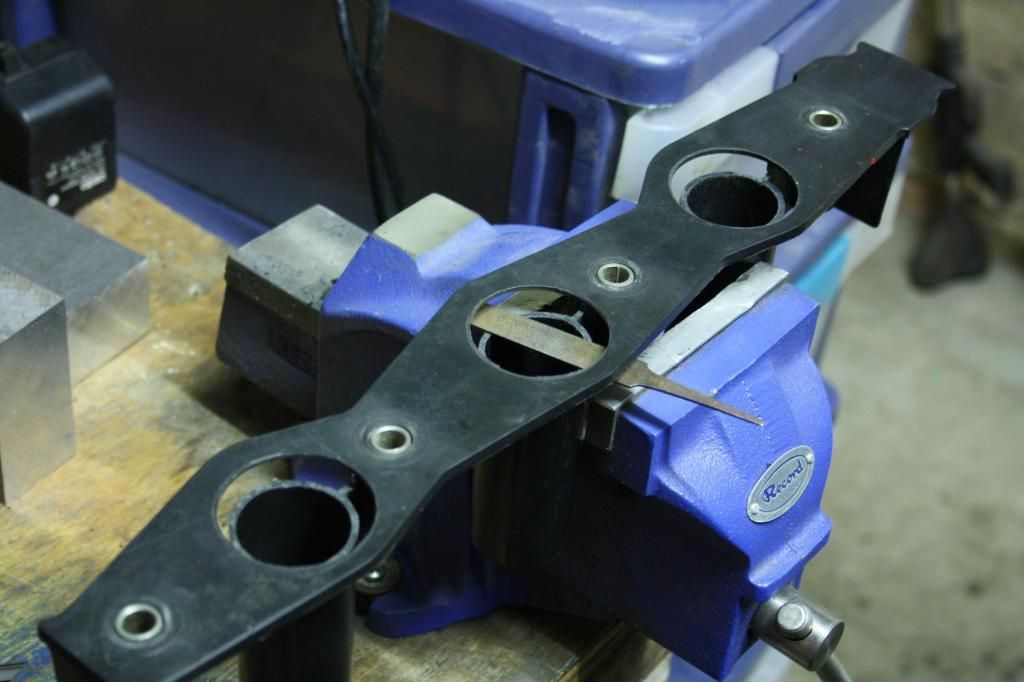
Unfortunately at the time of taking this on I didn't have a drill press, so I made a little jig to keep the hole saw centred.
fitting the guide up to get an idea... uh oh. piping sleeve is going to foul on the cam covers. this is why we test fit!
After a bit of head scratching including and not limited to contemplating flap wheeling out the covers, I realised the coil pack doesn't have to be dropped as low as planned. in fact it looked like it could be positioned so the rubber skirt was flush with the top of the guide, saving any sleeving. it's mad when you work out a new solution that is way way way less work.
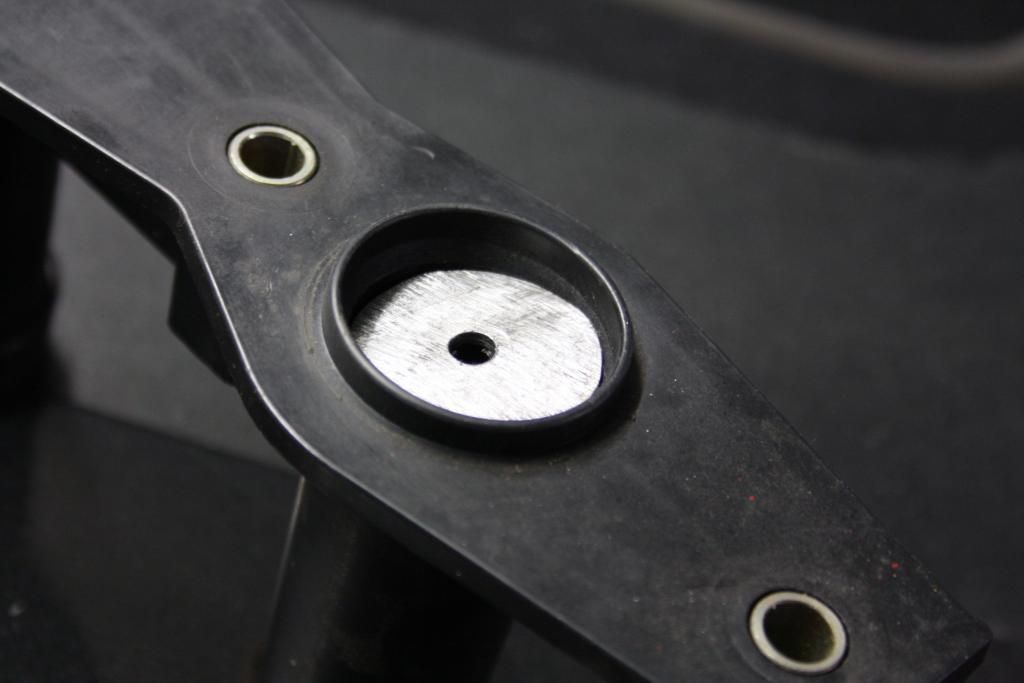
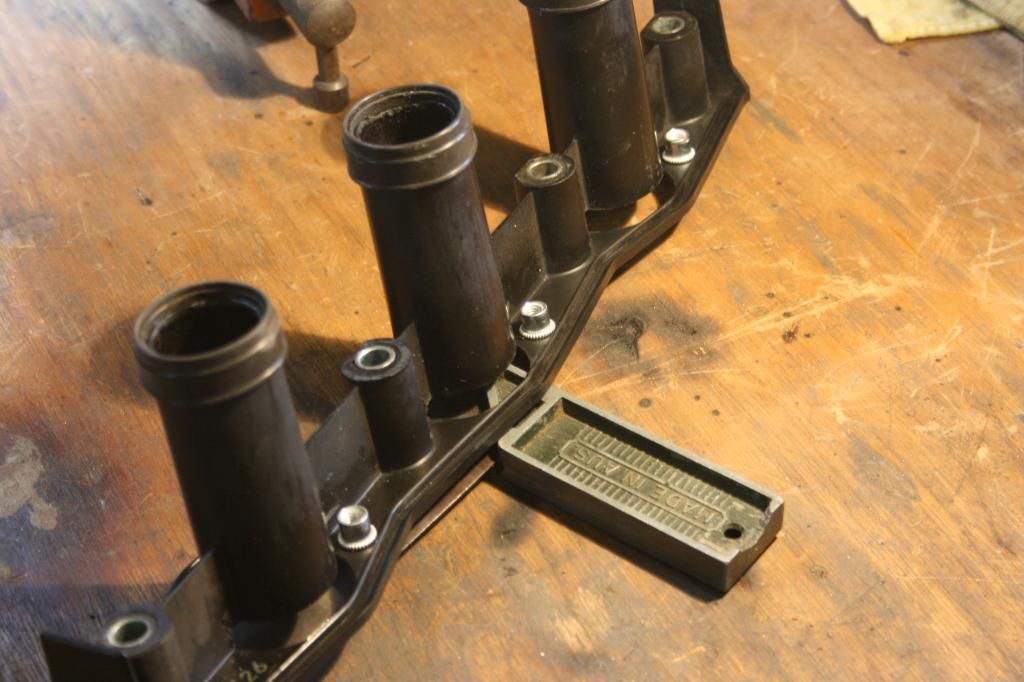
Cutting out a new guide with the perfect 46.2mm hole saw, was pretty lucky I had that lying around haha.
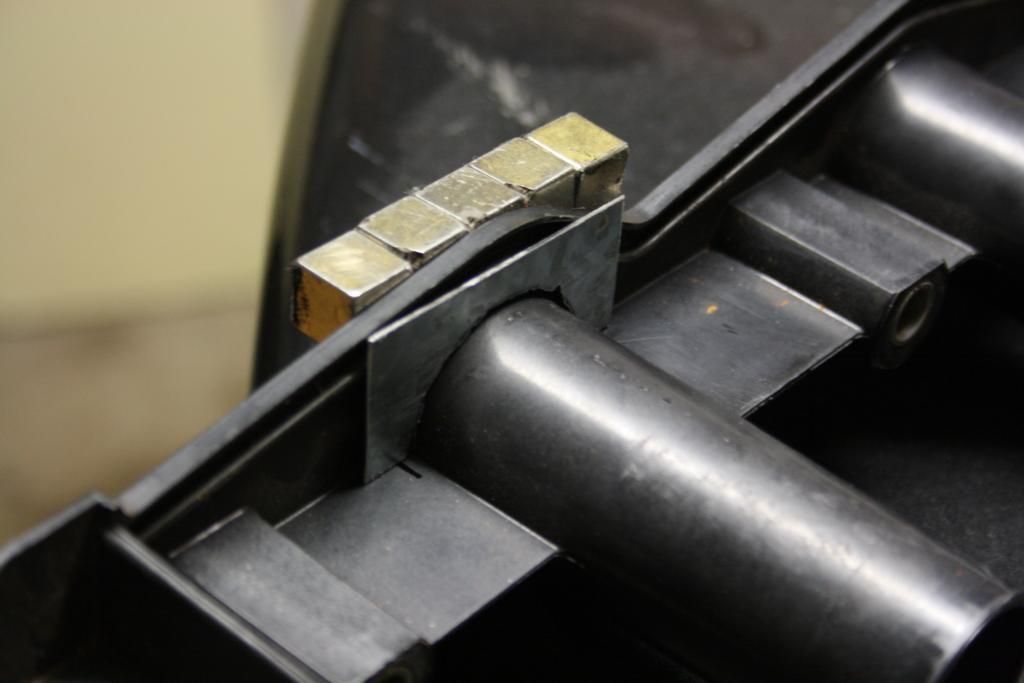
This meant getting pretty close to the seams the seals are mounted through, so some scrap secured with my super magnets (through the plastic) made sure everything stayed in tact as I did my thing with the grinder.
The tops of the tubes were then cleaned up with the most adorable little file you've ever seen
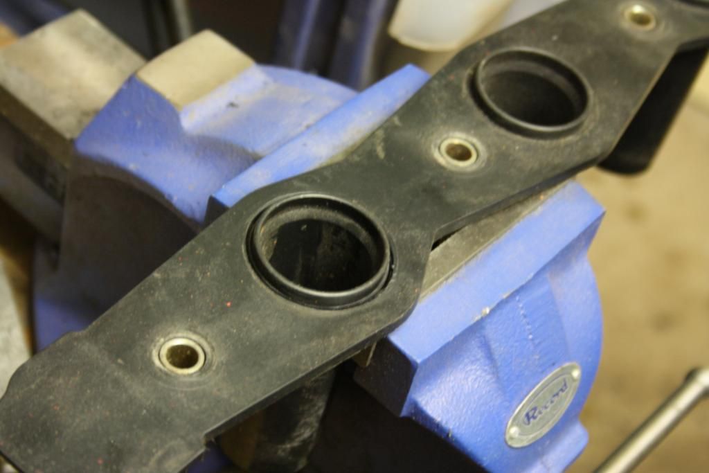
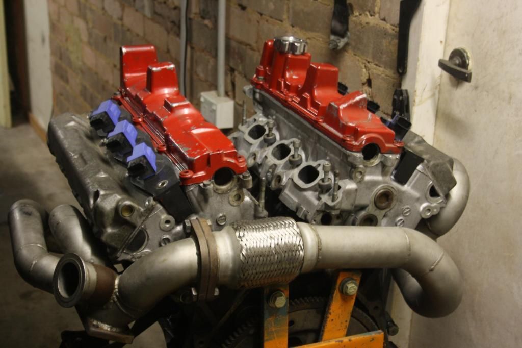
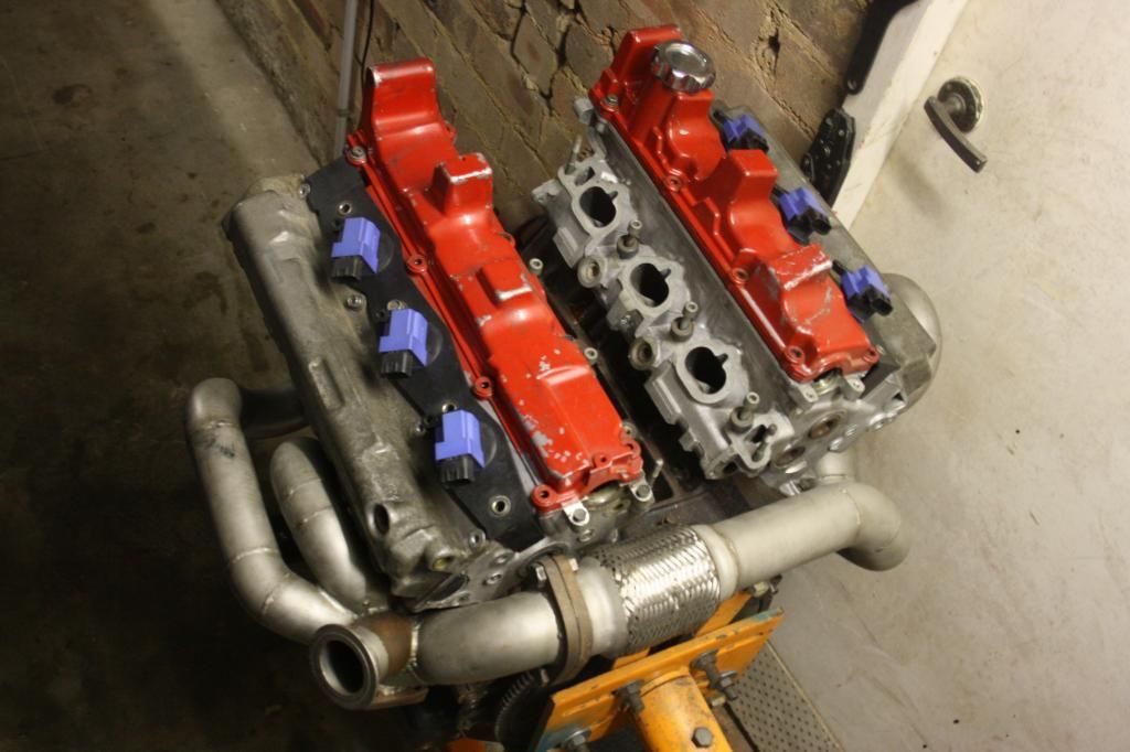
All fitted up.
The rubber skirts of the coil packs are hard up against the ID's of the freshly drilled holes and seal well.
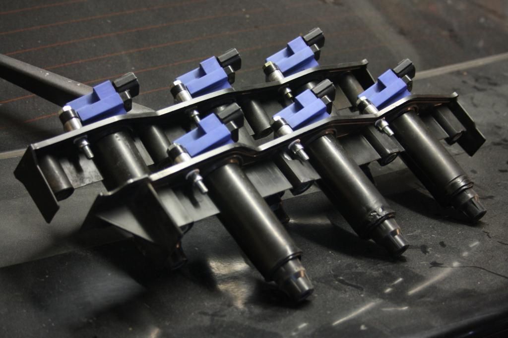
To hold them down I nutserted the guide.
I managed to snap one of the guides in a pretty repairable spot which meant starting again from scratch with a spare but eh... set backs are a necessary step before reaching your goal.
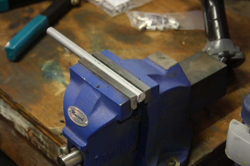
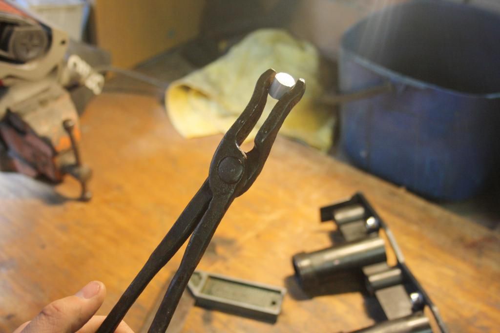
Ordered some solid 12mm aluminium rod to cut up and make into crush tubes. I use some genuine old school blacksmith cast iron tongs for handling material when hot, haha.
Still waiting on some hex key button head bolts to finish it all off nicely. Super happy with these, came together like they were factory.
 next step will be to modify these further to receive the radiator, which will be custom built and sit on the brackets.

Leave a comment: