If this is your first visit, be sure to
check out the FAQ by clicking the
link above. You may have to register
before you can post: click the register link above to proceed. To start viewing messages,
select the forum that you want to visit from the selection below.
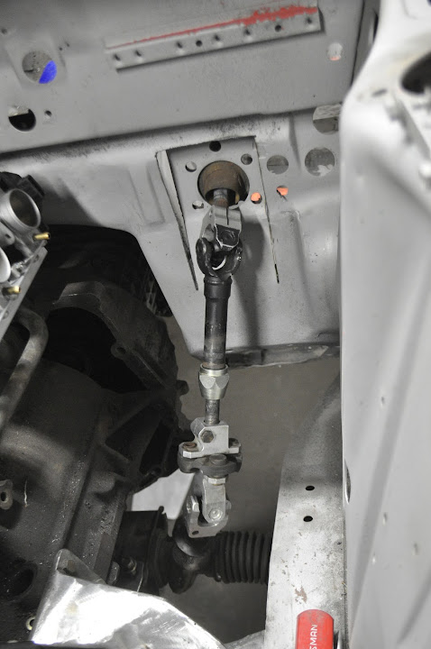
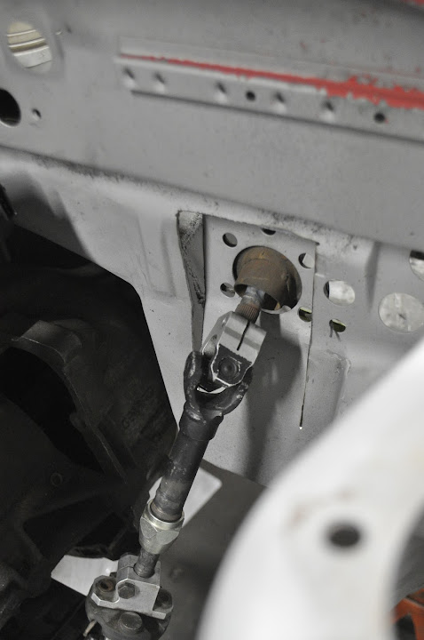
Small update from today. Didn't have a lot of time to put into her but I managed to get the steering linkage figured out. I only have pictures of the 'finished' product (I use that term loosely), but I basically just took the stock E30 linkage from my parts car and shorted all the sections of it so that the universal joints were closer together. Then I shortened the stock steering column.
I also needed to notch the firewall a bit so that the angle between the sections was small enough that the universal joints wouldn't bind. The lower one was fine, but the upper joint was very close.
I also need to add another support bearing to the middle section of the linkage. In the stock setup, the steering column didn't have any universal joints, it just ran straight to the steering box. Because of that the stock '02 steering column only has one point of support for the shaft itself. But now with the extra joint in the linkage the shaft has a bit of play, which the extra support bearing will take care of.
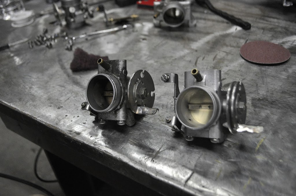
I decided to clean up the throttle bodies since they were pretty dirty when I got them. Can you guess which one is which??
5 more throttle later:
Here's a close up of the extensions I welded on the linkage tabs. Works great.
Then I worked on blending the modified intake manifold. This is how it looked when I started:
And after a couple minutes with a die grinder it changed to this:
And here is the same port with my spare gutted throttle body in place. I'm very happy with the overall taper and size, though I still need to fine tune a couple of areas. But I'm going to wait to finish them until I match the manifold to the head, which still needs to be ported as well.
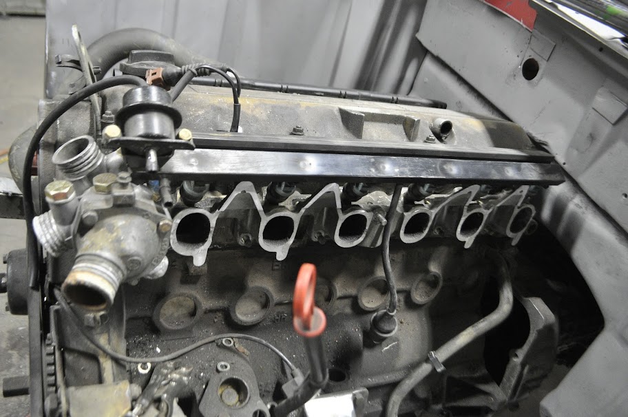
And here they are bolted in place in the engine bay. The nice thing with this setup is it doesn't get in the way of the stock fuel rail, pressure regulator, and thermostat housing. My original S54 setup had some clearance issues:
Then I had to reposition the dipstick tube. If you look at the above pictures, you can see the stock position puts it right between the first and second cylinder ports. With my plans for a plenum this would definitely get in the way. Luckily my largest bead roller die was the perfect diameter to the dipstick tube, so I was able to avoid pinching the tube at the bends. After a few carefully placed bends this is what I ended up with.
This new position should sit right between the intake plenum and the upper radiator hose.
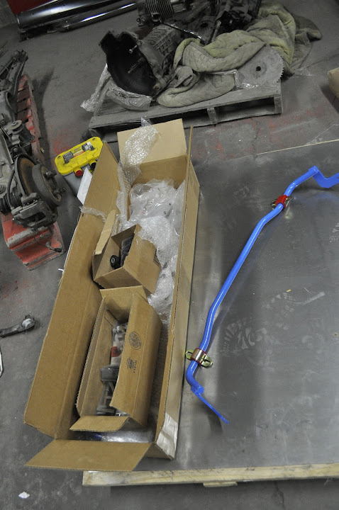
Picked up some more parts for her over the past week.
Euro Turn signals. These sit flush with the fender as opposed to the stock US-spec bits, which stick out pretty far to the side. They aren't brand new, but they will fit the patina of the rest of the trim nicely.
5-Lug Rear hubs and new rear brake rotors. These will round out the rest of the 5-lug swap (pared with the e12 front struts) and the rotors match the vented front ones that came on my struts.
Then I got a box of goodies from IE, including: Front and rear sway bars (2002 front, e30 rear), Posi-lock Camber and toe adjusters, New poly bushings for the front and rear suspension/subframes, and a lower oil pan baffle. These (plus the coilovers) will let me mock up all the suspension parts and make sure everything fits and works together.
I also got some work done on the itb manifold. In this first picture you can see the adapters I turned on the lathe to mate the stock 'i' manifold runners to the throttle bodies. They started as aluminum tubing 1.5" i.d. (~38mm) and 2.0" o.d. This will leave me plenty of material to help merge the ovalish shape of the runners to the circular shape of the throttle bodies. With all 6 made I tacked them in place on the manifold, 91mm apart.
If you look at the above picture, you can see how the 2" o.d. of the adapter is wider than the sides of the runners. In the picture below, you'll see that the inside of the runners are narrower than the i.d. of the adapter. In order to help these transition from one shape to the next I'll weld extra material to the outside of the runners. Then the inside can be ported out to the adapter diameter without worrying about making the walls to thin.
Here you can see the opposite runner with the adapter fully welded on. You can see all of the extra material welded on the sides to help build up the wall thickness. Also don't mind how ugly the welds look. The intake casting is full of contaminants, so no matter how clean the surface is as soon as I start my arc it just bring more crap to the surface. Aggravating to say the least.
Here is a close up of the adapters and the throttle bodies. You can see how the lip on the adapter mirrors the lip on the throttle body. This will let me use the stock rubber boots that BMW used on the bike to seal the intake tubes.
And here is the boot. I ordered 2 new boots (only 1 set of throttle bodies included them) and 6 more hose clamps that fit on each side of the rubber for a complete set. The rubbers have a step on the i.d. that grabs the lip on the throttle bodies and adapters that will help to seal and hold them in place.
Lastly, here you can see how the linkage works. The middle throttle bodies have the standard cable operated rotary linkage, but only one of them will need to be operated in that manner. To 'link' the rest of the throttle bodies to the cable operated one, the 'tabs' on the left sit in between the two adjusters on the right. Because the throttle bodies are 18mm further apart now, I just need to weld gusseted extensions onto the tabs (304 stainless) so that they will function as they used to. This will let me adjust the plate position of each throttle individually with respect to the others, and dial them in properly.
I've been second guessing myself for a couple of months as to whether or not the S54 ITB's are really a good fit for the engine, or more directly the 885 head. While they do give an easy solution for certain aspects of an itb setup (common vacuum rail, fuel injectors and fuel rail, proper spacing) I still couldn't ignore their overall size, and how that would effect the power curve of the engine. So long story short, I bit the bullet and ordered some new parts. Then I started machining the old 'i' manifold from my donor engine. When I got done it looked something like this:
The throttle bodies I will be using are from a late model BMW (keeping it in family of course) 1200RS. They are 38mm in diameter, and while some may argue they are to small for the engine, they will have no trouble out flowing the intake ports of the 885 head. This will help to keep charge velocities up, something that would have been lost with the monsterous S54 bits. Another plus of these throttle bodies is that they are mounted with 2 bolts on the top and bottom, so re-spacing them to fit the 91mm center distance for the M20 was as easy as drilling some holes in a piece of aluminum. Finally, because I'm using the stock M20 intake to interface with the head, I'm able to keep the stock fuel injector/rail location as well as the oil vent tube that runs down into the block.
Since they come in sets of four, I had to purchase two sets. Seeing as how I had two left over, I gutted one so that I could see how it would line up with everything without the throttle plate in the way.
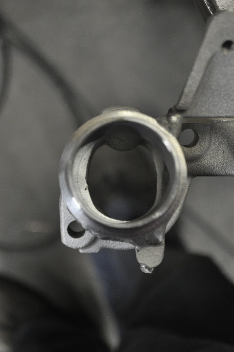
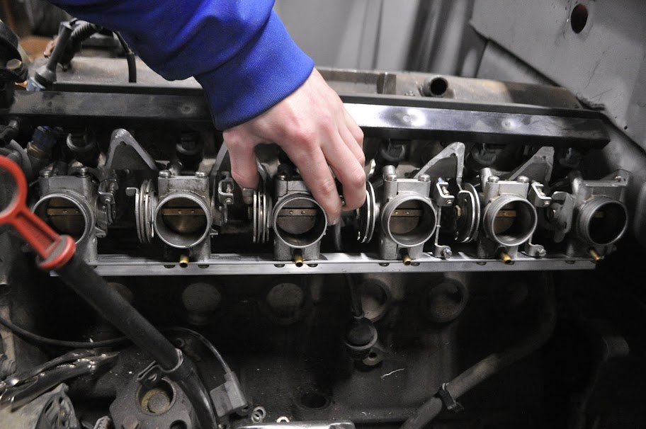
Here I'm holding the TB in place roughly where it will be. It looks fairly far away from the head in the picture, but it's actually only ~0.5" from the edge of the manifold. That will leave me enough room to weld the aluminum tubes in place that I will be mating to the throttle bodies. As you can see from the picture the port leading to the head will need to be opened up slightly and rounded out. However it should be a very direct and smooth path into the head.
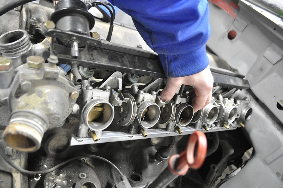
Then I took some aluminum angle and drilled the new mounting holes to properly space the rest of the throttle bodies. Then I bolted them onto the angle and held it in place.
I still need to weld on the new tubes onto the manifold, as well as extend the throttle tabs that translate the rotation from the center of the assembly to the outer throttle bodies. Overall I'm very happy with how they will look. The assembly will take up much less space than the S54 castings and throttle bodies, mostly because it doesn't have to open up the port from stock to 50mm diameter. This will leave me a lot more room for a proper plenum, which will either be aluminum or composite. It also puts the throttle bodies themselves much closer to the head, which will lead to better throttle response.
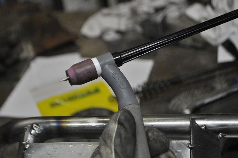
Not what was in the 4 big boxes, but I got a new TIG torch, with a flexible head. Very handy for getting into tight spots or just making a more comfortable welding position.
And with it I finished gusseting the hood mounts.
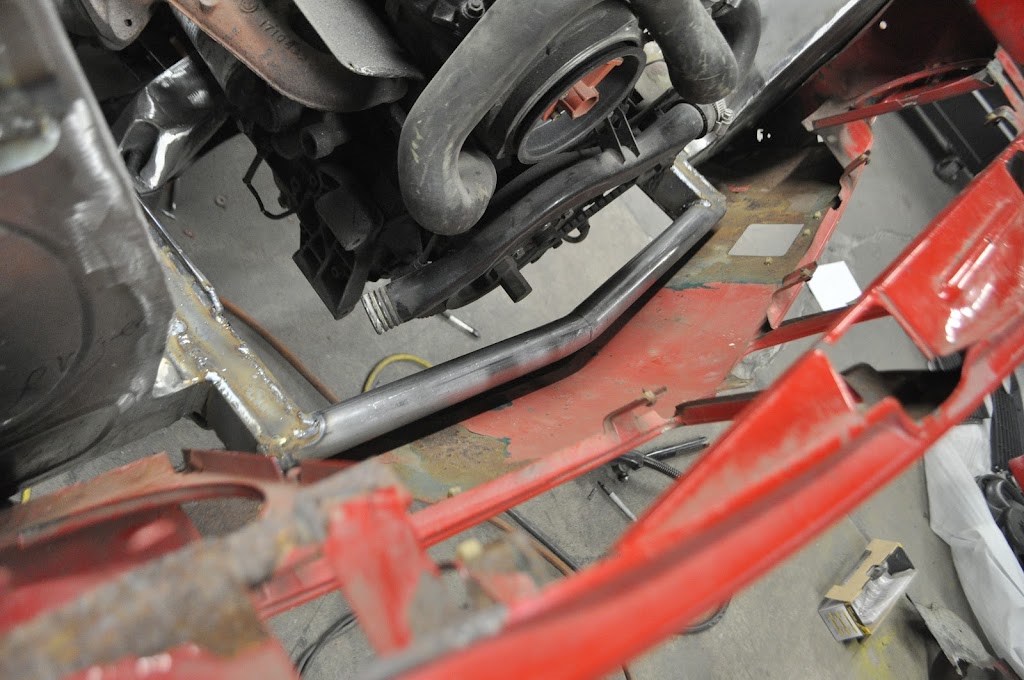
Then to finish off the night I fabricated the mounts for the oil cooler and radiator:
The upper OC mounts are just tabs that come off the front support bar:
The radiator mounts to the tie bar, one on each end. I will also be making an upper support bracket to hold the top in place.
Nose panel bolted back up with everything else in place:
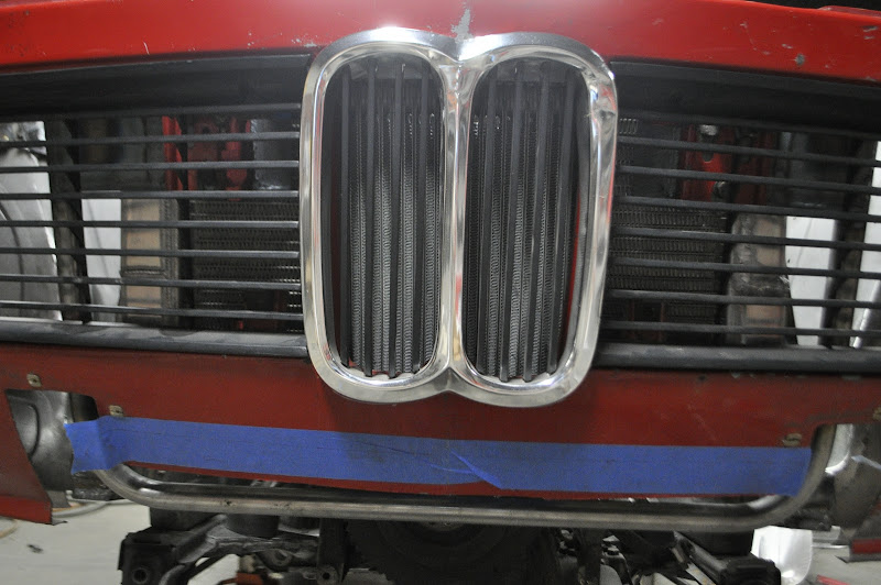
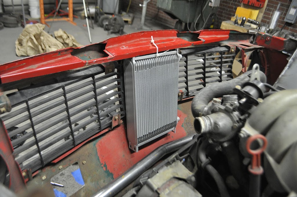
Here you can see the oil cooler behind the kidney grills. Worked out well with the cooler on it's side, the slates are vertical and match the lines of the grill.
Next up is the fab the lower oil cooler mount (it's only bolted in by the top right now) and the other radiator support. Then I will brace the mounting points on the front frame assembly and strip the nose panel for metal repair and some bracing.
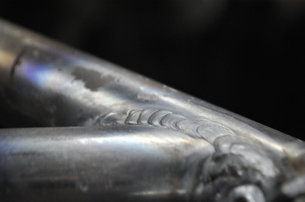
Happy to say my TIG work is starting to look better. I've decided that I'm going to TIG everything that I reasonably can (assuming the welding position isn't crazy or that the material is to thick for my welder). While it does take more prep and time compared to MIG, the welds themselves just look much nicer. There is also much less clean up work, with no splatter and less warping in most cases. These are from the front bracing I did this weekend:
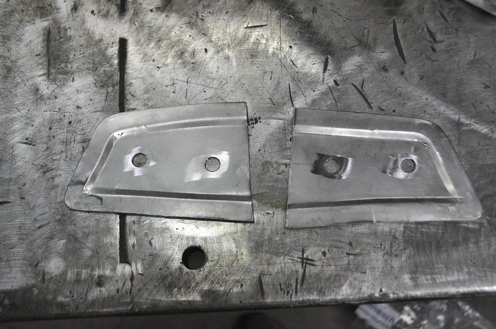
So with the front clip as gutted as it is, it obviously won't be able to support the weight of the hood like it used to. And the front hinged hood was one of the original parts of the car that I didn't want to loose, so next up was figuring out how to fab up new hinge mounts. First I made two plates that mimicked the stock nut locations.
Front:
Back:
With those done, I mounted each side and tacked them in place with the hood in the down position:
Then I checked to make sure the axis of both hinges are still in line so the hood would open properly:
View of the hinges from the engine bay. I still need to add a lot of bracing/gussets to add strength, but they can support the hood fine even though they are just tacked in place.
And here's what the hood looks like mounted in place without front fenders or front clip. Because I can.
Now that I have the hinges in place I can work on mounting the radiator and oil cooler. I wanted the hinges in there first since they have to be in a certain position, while the radiator and oil cooler can go anywhere so long as they fit and don't interfere.
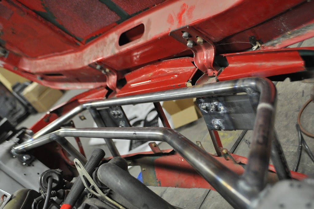
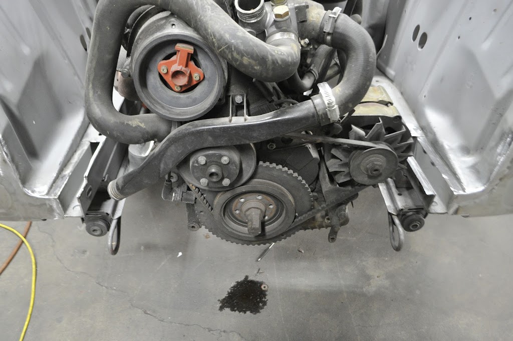
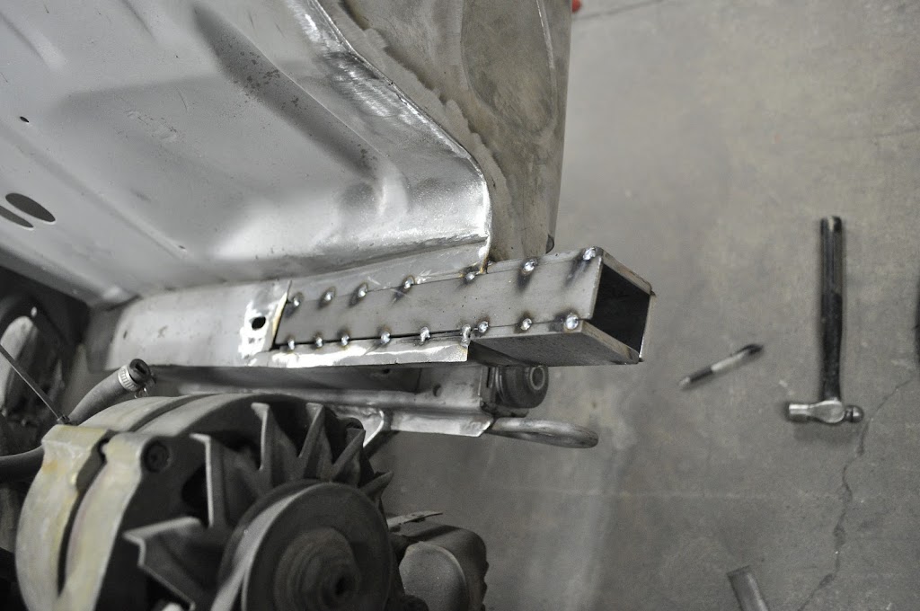
After thinking about it for a couple days, I decided I wasn't happy with my initial frame rail brace. The main reason for making the front clip removable was to make maintenance easier to do. But because the brace was welded in place, it meant that I would still need to lift the engine out of the car, or lift the car over the engine/subframe. Both of which can be a chore if you don't have access to an engine hoist or really tall jack. So I decided to cut it out and design a better solution. After a long day/night of measuring and fabrication, this is what I came up with. I only have two pictures right now, I'll get some more detailed ones when I'm not as tired.
It is completely removable, and gives me a sturdy frame to mount the radiator and oil cooler to. I should be able to run some lower bracing to the air dam in the front and hang the intercooler from the lower bar when that time comes. I will also have the strut bar tie into the top bar when I get that fabbed together. Here you can see how it clears the front clip at the top:
With this TIG'd together up next I will get the radiator and oil cooler mounts done. Once those are in place I will make a cover plate that goes over the top of the front frame section, mimicking the stock '02 sheet metal front end with a cutout for the radiator fill cap. I'll probably use sheet aluminum though, the front end is heavy enough already lol.
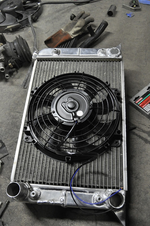
Got a couple new goodies in the mail today. First up was an order from Summit Racing. Gotta love being in Ohio, one day shipping for the price of ground. This order included the radiator fan so I can get the radiator mounted and ensure I have enough clearance between it and the front of the engine.
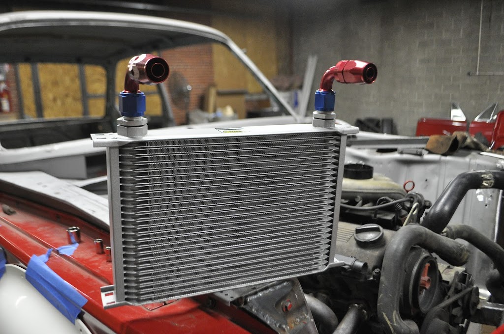
I also got my Earls Performance Oil Cooler. This will let me ditch the stock E30 cooler, which doesn't really work very well to begin with. It will also let me relocate the assembly up higher, away from rocks and other road debris. The cooler is 13"w x 7.75"h x 2"t, which give almost double the effective surface area as the stock cooler.
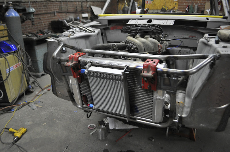
Here you can see the radiator, fan and cooler in place. The cooler fits in the nose panel directly behind the kidney grills, then the radiator sits on the bottom cross member angled forward slightly. The fan has a minimum 3/4" clearance between it and the engine all the way around.
Here's the business end of the coolers. In retrospect I kinda wish I'd gone with the black one, but I'm sure it will look fine once everything else is in there. On another note, I wonder if anybody has ever left the diving board mounting holes and just used that to run charge piping to a huge front mount intercooler... I suppose that would kinda kill the 'sleeper' theme though.
And here's the position the Oil Cooler without the radiator in place. While the zip tie is a very high tech solution, I will be fabbing up some tabs off of the inner tubing structure for it to mount to.
The next set of parts that came in were my E12 front strut assemblies. Now why on earth would I want those some people may be asking. The 'short' answer is as follows:
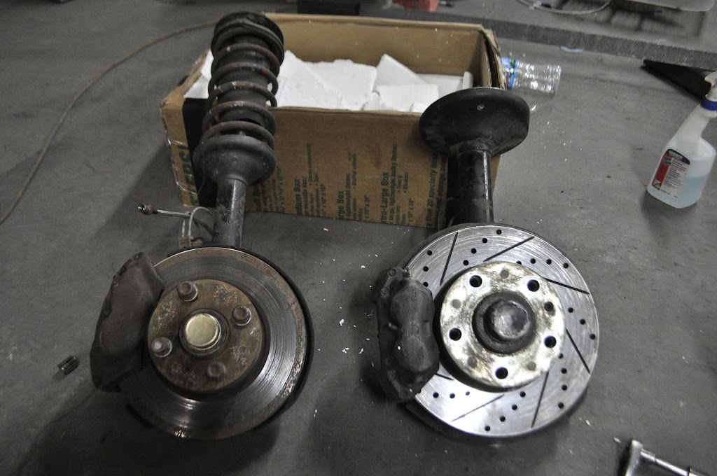
1) Big Brakes on the cheap - even larger than the 'volvo' bbk (280mm vs. 272mm) and 100% OEM BMW
2) Larger Strut Tube - The strut tube I.D. is larger than that of the '02, which means you have MANY more choices for strut inserts, including the Koni Adjustable Race pieces (hint hint). And the O.D. is still small enough that the GC Coilover Kit for an '02 will still work with them.
3) Tii Bearings for non-Tii Prices - The E12 shares the same larger bearings as the much sought after Tii spindles, only they don't cost and arm and a leg to buy. I was able to find the entire strut assemblies (including brakes and hubs) for under $200. To get even close to the same outfit with Tii bits would normally run upwards of $600.
4) 5 x 120 Bolt Pattern - Now this may seem very unnecessary to some, and to each his own. Personally, the switch from 4 to 5 lug is worth it for the options in wheels alone (as you'll see next week). There are many old classic 5x120 wheels in 15" and 16" from the big coupes and sedans that sell for a fraction of what the 4 lug version do. It also opens up a lot of newer modern BMW wheels (if your into that kind of thing). I will also say the decision was easier for me due to my E30 rear subframe, you can swap Z3 hubs and brakes back there and your done.
Here you can see the regular '02 strut on the left with the 'volvo bbk' and the e12 strut on the right with it's standard size brakes (cross drilled/vented not std):
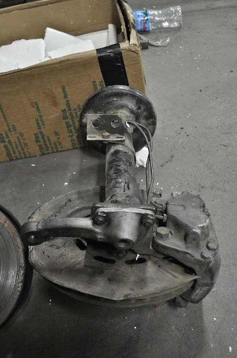
Now when trying to fit the E12 struts to an '02 there are two places that they need to connect to the car, the upper strut bearing and the pitman arm/lower ball joint. Since I'm running coilovers the upper strut bearing will be simple enough, just a set of '02 camber plates. However the pitman arm is a bit more tricky, or so I thought. The pitman arms on 2002's mount with three bolts (M8) and are aligned by a groove that is machined into the center of the arm. A matching lip on the bottom of the strut housing keeps the pitman arm where it needs to be. The E12 uses the same system, however it's held in place with three M10 bolts. Luckily, the groove and lip on the E12 parts is the same width and depth as the ones on the 2002 parts, and on closer inspection the top two bolt holes line up perfectly between the two struts. The third mounting hole is actually a couple of mm further down on the E12 part, but a couple of minutes on the mill and I was able to drill out the M8 holes to fit M10 bolts, as well as space the third hole down to where it needed to be. This left me with an E12 strut assembly with the 2002 pitman arm, ready to bolt onto any 2002 front subframe!
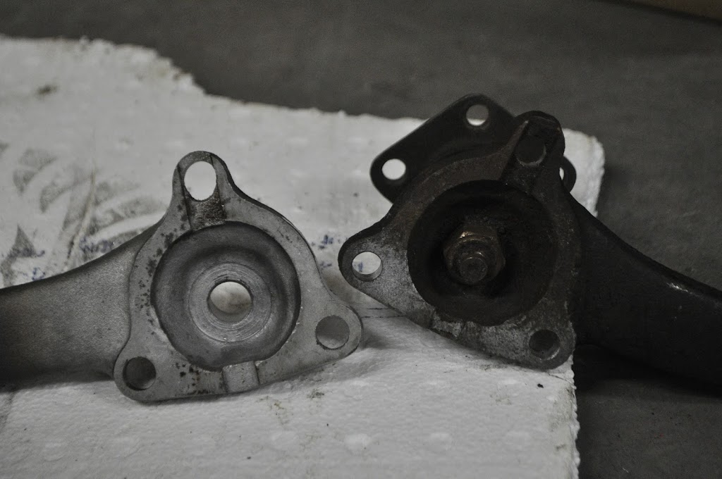
The pitman arm in the above picture is one of the shortened arms I have for the e21 steering rack swap. Which brings up another benefit of the E12 setup. On the 2002, the brake caliper hangs off the back of the strut, while on the E12 it hangs off the front. When shortening the pitman arms for use on the 2002 strut, the tie rod end mounting point was moved very close to the brake caliper body. You can see in the above pic how the pitman arm and caliper are on opposite sides of the E12 strut housing. While the location on the '02 strut isn't a harmful issue, it is much nicer to have more room to get to the tie rod ends and brake calipers for maintenance.
Here you can see the modified pitman arm on the left and a stock arm on the right. As you can see there is still plenty of material around the edges of the arm considering the types of loading it will see.
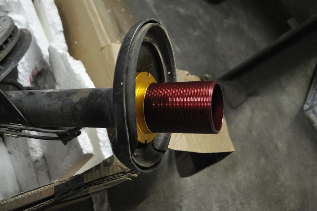
Here are my GC coilover sleeves slid over top of the E12 tube (yea I still have to cut off the stock spring perch). A nice thing to note is that the sleeves actually fit perfectly around the E12 spindle tubes with very little slop (maybe 0.03"). The '02 spindle tubes are much skinnier, and so they would require a spacer to be very secure on the tube.
I will also be making/buying a bump steer spacer for between the strut housing and the pitman arm. This will help to return the front suspension to the proper geometry on a lowered car.
Then I cut a new hole on the opposite side and welded the new outlet in place:
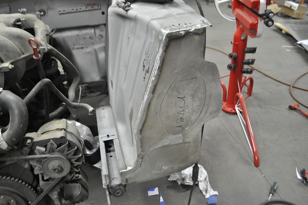
The last thing to do was to make the internal baffle to make the coolant flow through the plates instead of just down to the outlet. so I cut out a section so I could access the middle of the driver side tank:
Then I made a cardboard template for what I wanted the baffle to look like:
Template turned into aluminum baffle:
Baffle welded in place:
With the baffle welded in place I put the cutout section back in place and welded it as well:
Here's is a pic of it while I was doing the leak test. Luckily for me all my welds held! No leaks. Now that I know my welds functional I just have to work on making them look pretty lol.
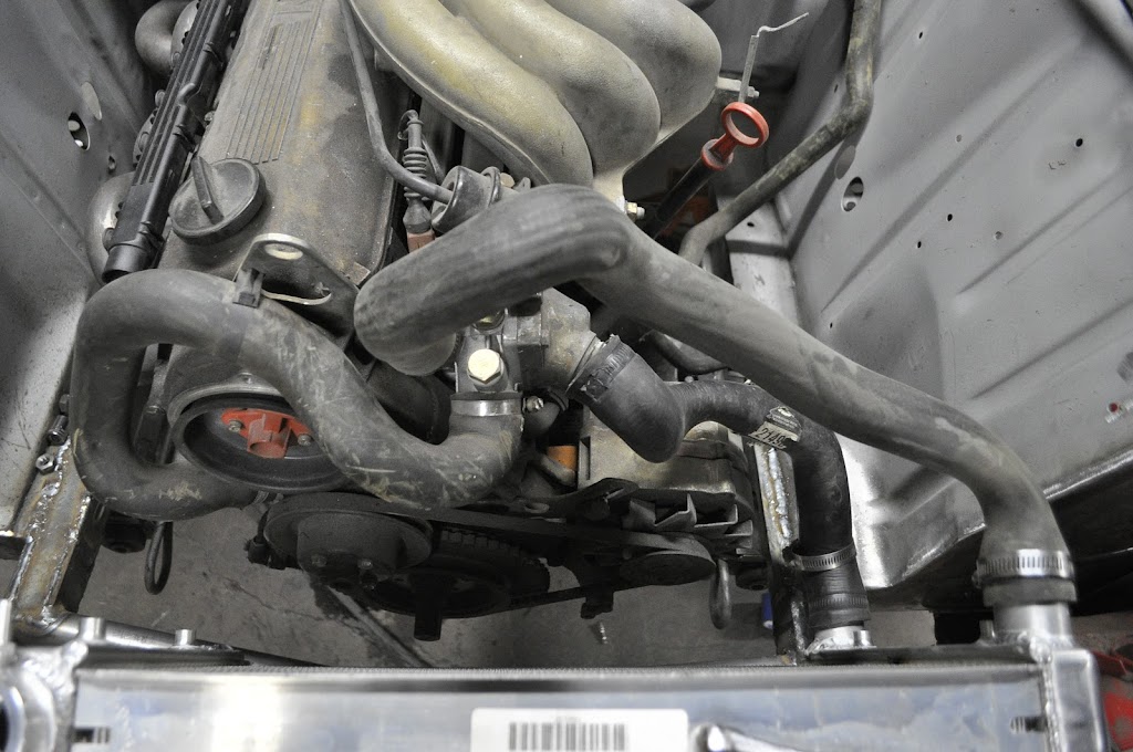
And here you can see how the modifications simplified the routing of my coolant hoses. I wish I could do something to move the water pump -> thermostat hose, I may try to fab up a hardline of some kind, but I'm not going to worry about that for now. Also, ignore the wonky bends in the coolant hoses in the pic, I just used some I had laying around. I'm going to try and find some more universal silicone ones that match the needed paths better.
I suppose it was a fairly hard thing to guess lol. Not many BMW's are running 6 LSX coils.
I decided to use these over the normal BMW Coil-on-plug for two main reasons. First, the m20 doesn't have a very elegant way to mount a COP setup. It has been done, but since the spark plugs are on the side of the head it normally looks a bit hacked together. Second, since I'm using MS3X for my engine management, the LSX coils can be wired directly into the ecu. The BMW coils need a separate circuit to drive it, so simpler ended up being better.
Here you can see how I angled them on the mounting board. This will let the plug wires be run nicely along the firewall over to the engine.
Also, this was my first real part from aluminum the included welding. Overall the welds are getting better, but I have a long way to go. I put to much heat into it in a few places, but I'll blame at least some of that to trying to weld 1/8" sheet to 1/2" tabs.
And here is where I will be mounting it in the engine bay. I'm hoping to be able to use the stock plug wire holder (slightly modified) or make a new one that mimics it's function. That will keep the wires from draping across the valve cover or falling down onto the headers.
I swear those headers look better everytime I look at them...
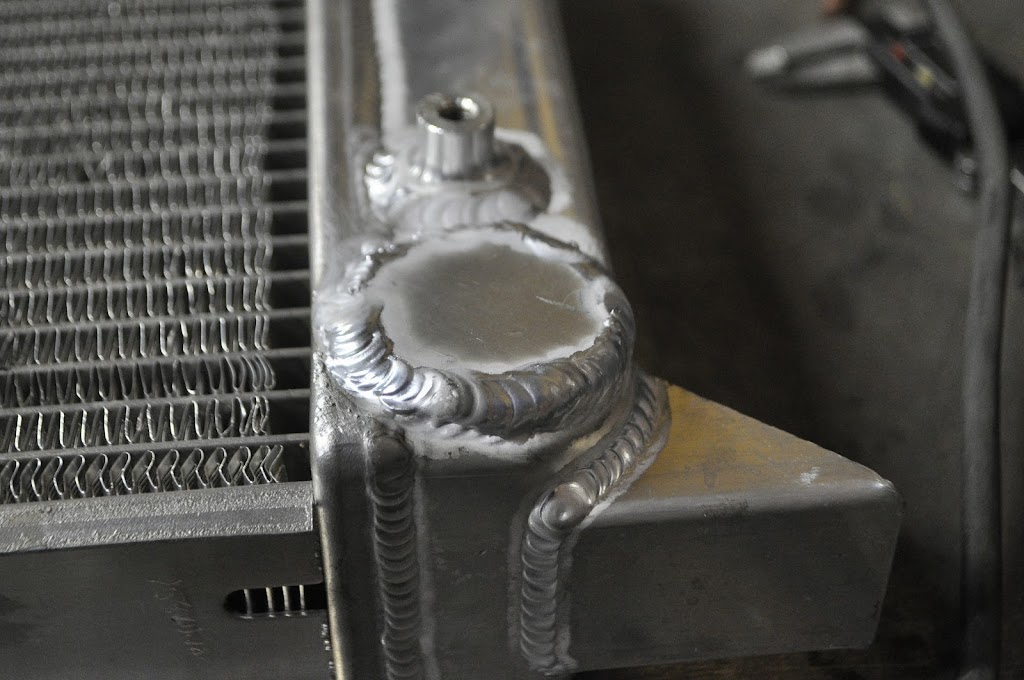
Next up on the list was to tear into a perfectly good radiator. I bought it back before I figured out how I wanted to run my coolant hoses. Now that I've figured that out, of course the outlet for the radiator is on the wrong side. In order to fix this, I cut off the outlet from the passenger side.
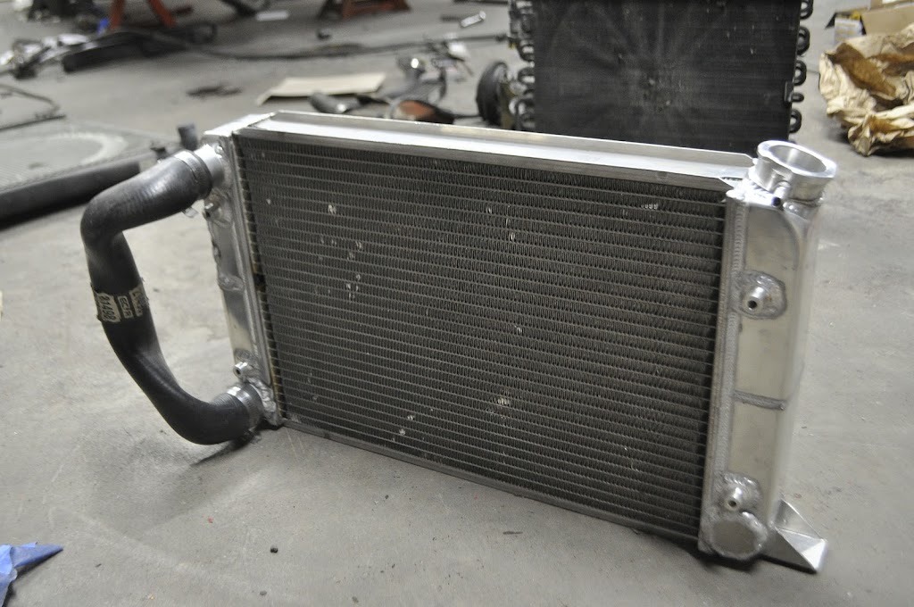
Next I'll make a plug for where the outlet used to be. I also had to reduce the diameter of the outlet from 1.75" to 1.5". To do this I just cut out a section and welded it back together. Here you can see that the inlet and outlet are the same size, like on a normal M20.
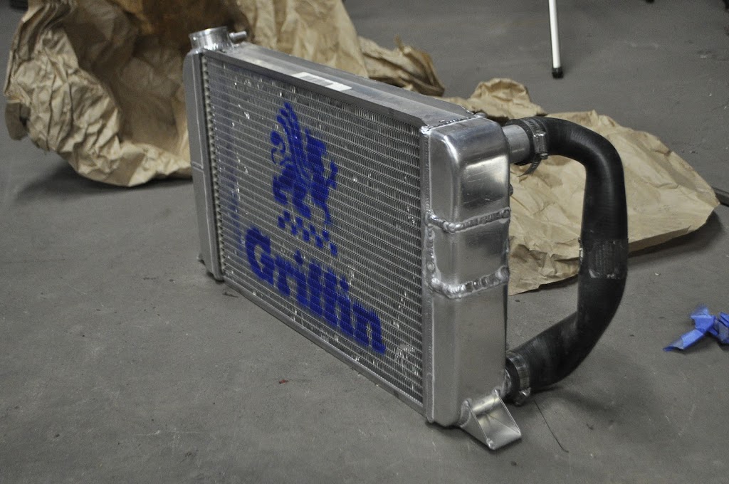
And here you can see how it will be once I weld the outlet in it's new location. The last modification I will have to make is a small block off plate that goes in the middle of the driver's side. This will direct the coolant from the inlet -> across the top half of the radiator -> down the passenger side reservoir -> back across the lower half of the radiator -> out the outlet. I didn't feel like going through the heat transfer equations to see exactly how this would effect the cooling, but considering Griffin Radiators also offers the exact same setup I'm making now (if only I would have bought that to start with) I'm sure it will work just fine.
Now the the front clip sheet metal won't be in charge of supporting the structure at all, I needed to tie the two front frame rails together again. This is how they looked after removing the brackets for the 'diving board' front bumper:
Passenger side, prepped with weld-through primer and ready to be patched:
Extendsions tacked in place:
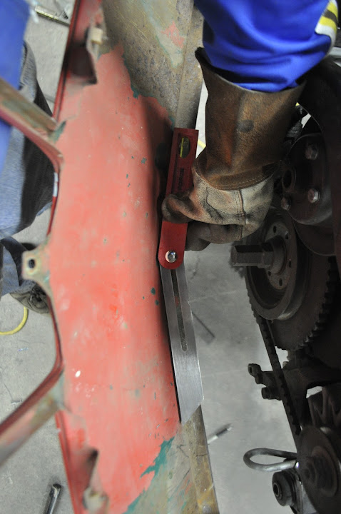
With both sides tacked up, it was time to make up the cross bar. I decided to use the same 1.5" DOM tube that the roll cage will be made from. The first step was to measure the angle needed to fit the nose panel:
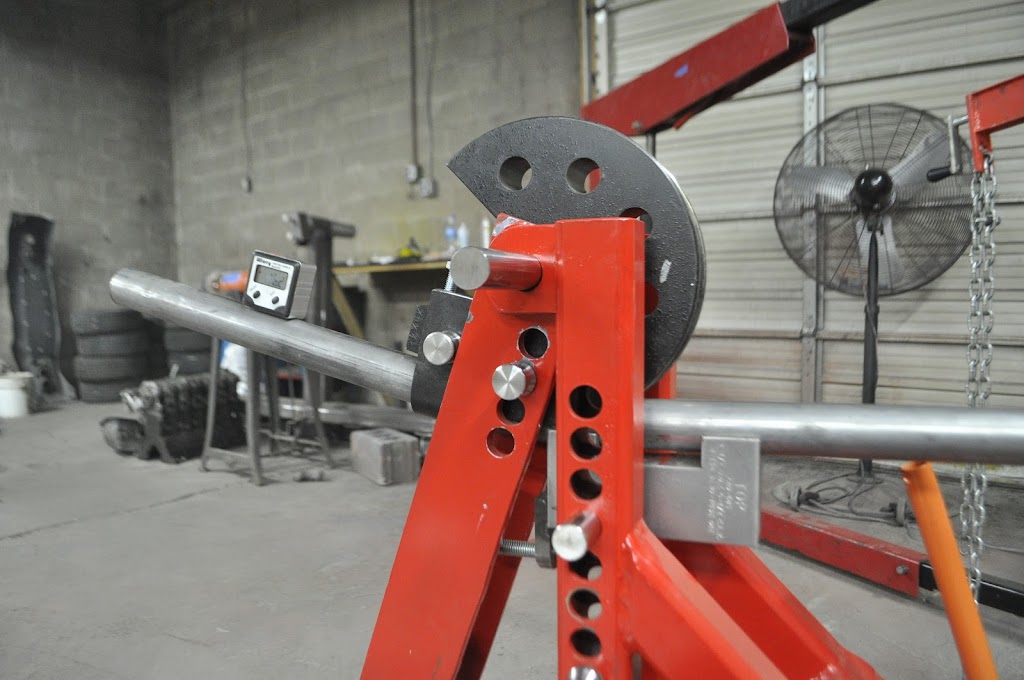
Then I used the bender to bend stuff:
Then I cut and notched the tubing to fit onto the front frame rails:
And here's how it fits with the nose panel in place:
With the cross bar in place the next steps will be to mount the radiator and figure out how I'm going to run the coolant lines. I also need to get the last turbo flare ordered so I can mount the front turbo parts and make the necessary body modifications.
Then I decided to take a break from the body/frame work and work on some of the other things that need to happen in the engine bay. Any guesses as to what this guy will be for??? 10 internets to anyone that gets it right.
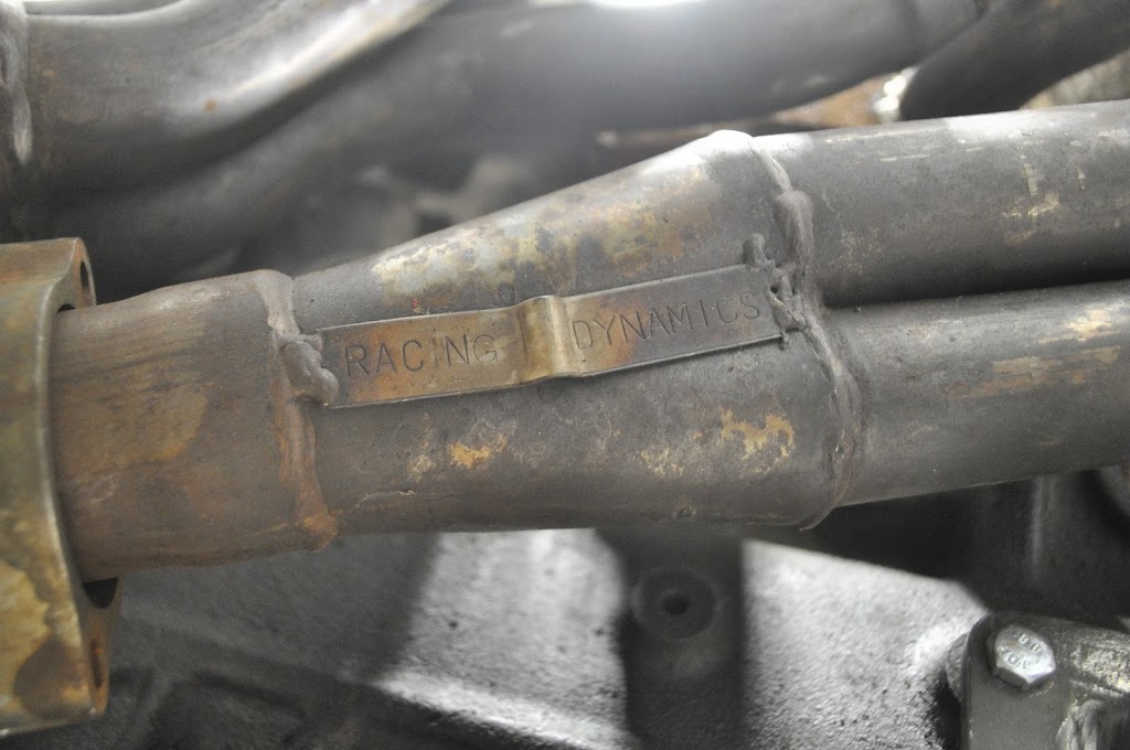
Last but not least I got a nice surprise in the mail today:
I got a smoking deal on a set of original e30 Racing Dynamics headers. Having only had one set of 'ebay' headers in the past I must say the quality on these is really great. I was very afraid that they wouldn't fit in the '02 engine bay, but turns out they are compact enough that there is plenty of room. I was able to get them for a steal, and I'll probably get them ceramic coated at some point. Some more pics of them:
Here you can see that I had to flip the Oil filter housing 180 degree's in order to get it to fit with the new headers. In the end it works out great because it puts the oil filter in an easier place to get to, I can take it off very easily without getting under the car.
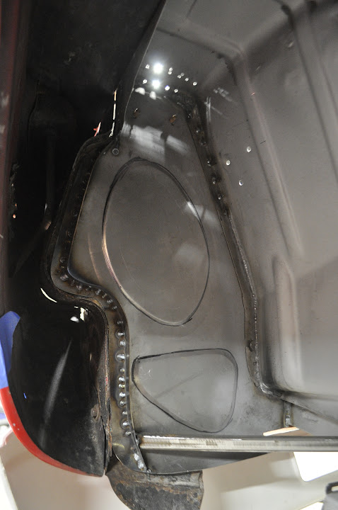
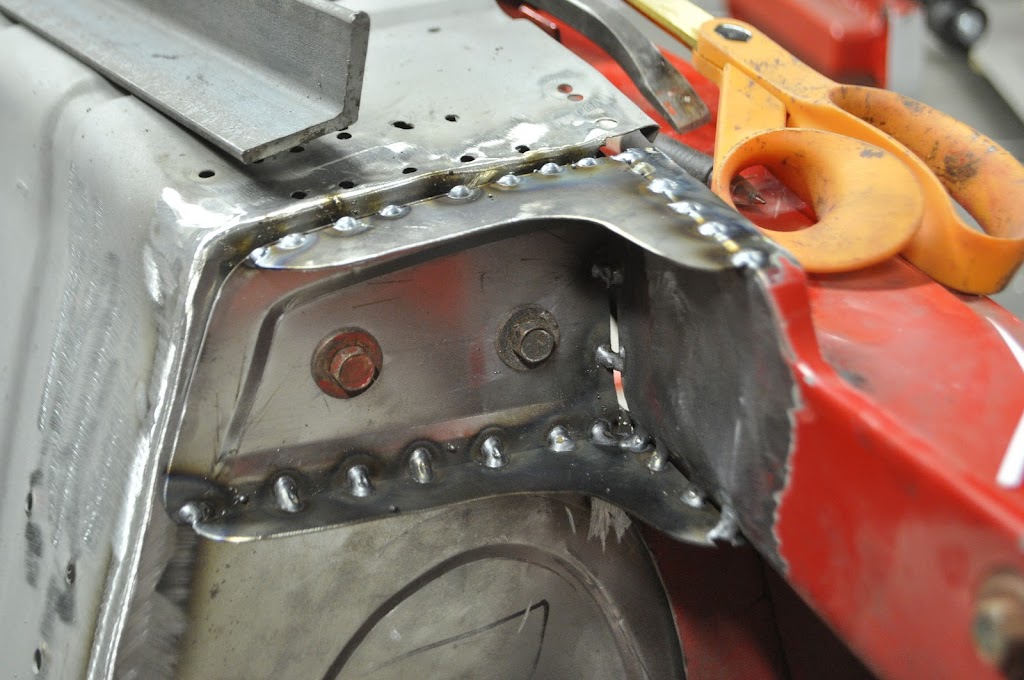
Finished up the front clip mounting points tonight. Where we left off last time was here, with the new front wheel well panels welded in place:
Then I added some bracing to the rear of the new panels. This ensures that they will have the necessary sturdiness to not move around or deflect as the car drives around. The bracing consists of two parts. First I welded a strip of 18ga x 0.75" metal down the outer edge, then triangulated the lower outside corner to the frame rails with some thin wall square tubing.
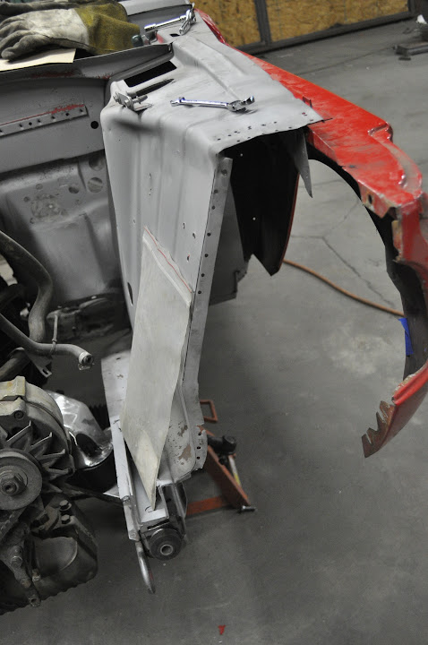
Then I remounted the front clip so I could locate the new mounting plates and holes.
Then I made up the new mounting tabs. This will be welded onto the front clip and attach it to front panels of the wheel well.
Test fitting before welding in place:
Drilled the mounting holes in the tabs. Once tacked in place I can transfer the holes to the chassis so I know they will be in line.
Here are the new mounting plates welded in place. As you can see I also made upper and lower braces to help strengthen it. How the passenger side looks:
And the driver's side:
I also got some goodies from the fatherland in this week. A bunch of new fasteners:
And new sheet metal for the rocker panel area. Now that I got these in I can locate the rear fender flares and finish up that area of the car.
Last but not least, a little teaser. I've got some goodies coming in the next week that should really start to pull the car together. No pics yet, but the waiting is half the fun lol.
Finally got started on the removable front clip. I've been trying to think about how to do this for a while now. There are probably a bunch of ways to do it, but this is the best way I could come up with and I think it should turn out pretty nicely. The first step was to clean up the edge where the old nose clip was spot welded on. With the edge straight and clean, I applied some weld-thru primer to the areas that would be overlapped with new sheet metal to help prevent future rusting.
This is where the front clip was spot welded in place.
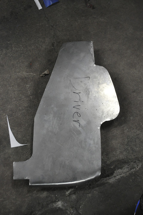
With the edges cleaned up I needed to make a template for the new metal. This section is important because it helps to block off the front wheel well from the headlight area and engine bay.
With the template made, I could transfer it to my 18ga metal and cut out the driver side plate.
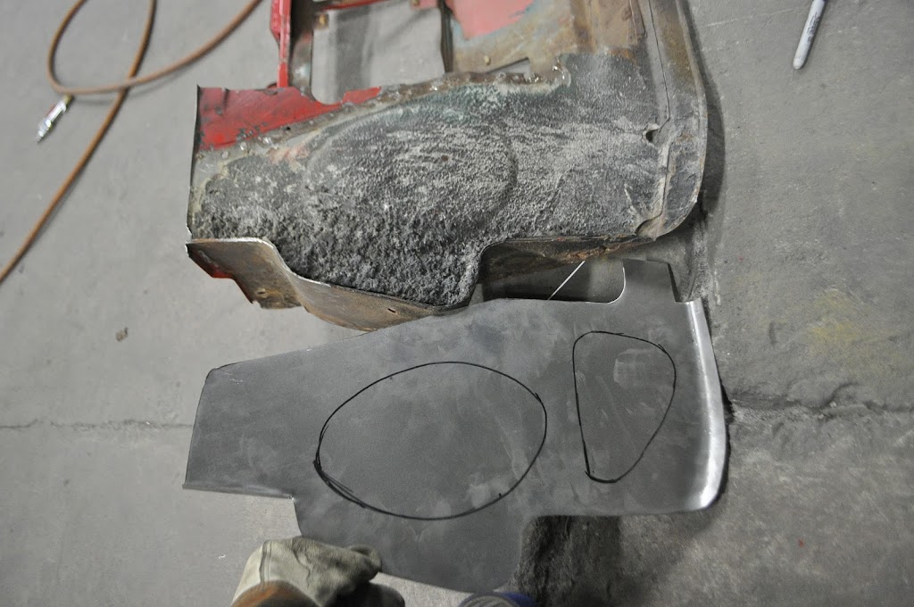
Now just a plain sheet of 18ga isn't very strong. So in order to add some strength I decided to roll a couple 'dimples' into. These also mimic the OEM plate.
Traced the pattern:
Rolled the dimples and the welded in place:
And welds ground smooth.
Now here is a rough example of how the front clip will bolt on. I'm planning to use the same type of fasteners that hold on the fenders, and so I will have a bit of adjustment to help make sure everything lines up. There will be two screws in the tab along the top of the nose panel, as well as a couple of connection down along the bottom edge. Also note that the nose panel will no longer be a structural panel of the car. I will be adding more bracing across the engine bay, welded in place along the bottom edge and then a separate piece that bolts into the top that is incorporated into a strut bar assembly.
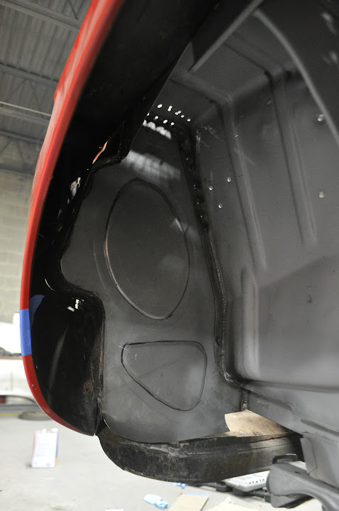
And here is a view from the inside of the wheel well. As you can see it still creates a barrier between the wheel area and the engine bay (the light you see coming through is from some rust holes that I still need to patch on the nose panel).
Then it was onto another round of plastic surgery on the nose panel. Not much left on it, but it doesn't need much either. I'll be adding some light bracing in strategic places once it's bolted back up and I know it's true and straight. As far as weight the only thing that it needs to support now is the headlights, grills and part of the front turbo lip.
To finish up the night I knocked out the passenger side panel. I still need to do some trimming along the outer edge so the nose panel can fit up tight to it, but it looks good so far.
I was originally planning to work on the removable front clip today, but some other parts came in the mail so I shifted gears. What did I get you may ask?
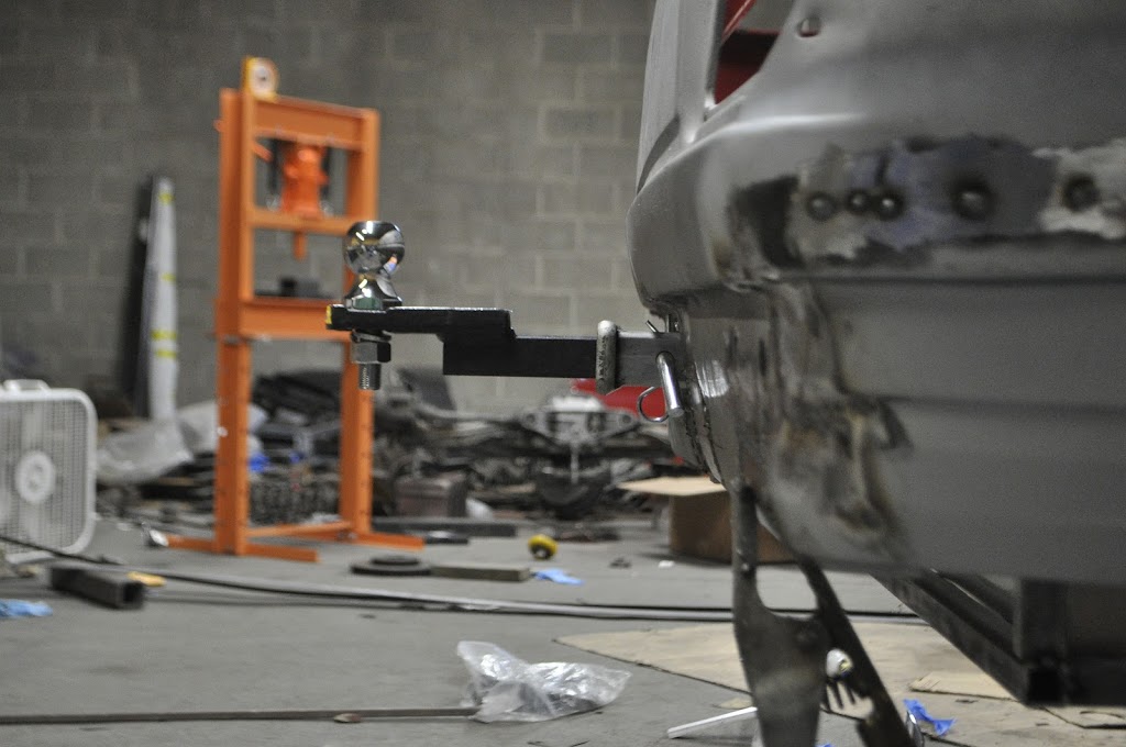
A Class 2 trailer hitch and receiver of course!
As any of you that track your car know, normally you want to take spare tires, tools, jacks etc with you. Adding that to the fact that I want to be able to use the car on trips and vacations, the ability to haul a small trailer makes it much more practical. The Class 2 set up is rated for 3,500 gross trailer weight and 300 lbs tongue weight, which will be plenty for anything I ever need to do.
One of the biggest challenges with the hitch was figuring out how to package it with the center exit exhaust in the rear. Originally I was planning to have a fixture for the receiver that would bolt up to the underneath of the trunk frame. While this would have worked, the fixture would have been VERY heavy and a pain to store when not in use. Also the packaging of the exhaust around the fixture would have been difficult, leading to the receiver being very low or very far from the rear edge of the body. Luckily I was already building up a new trunk frame, which gave me a better option.
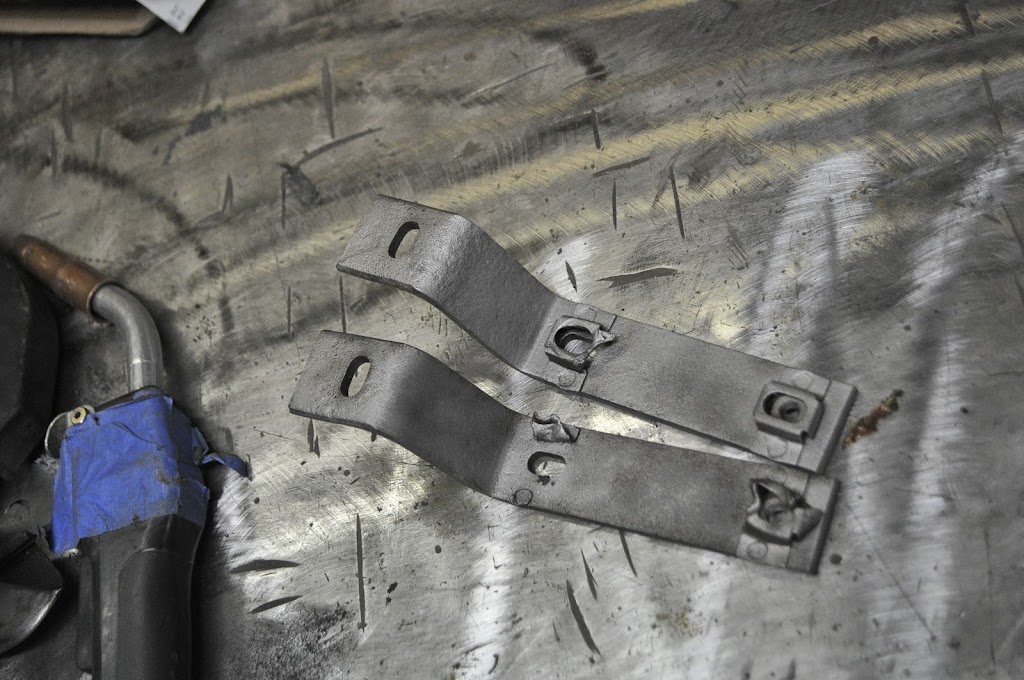
The first step was to clean up my bumper brackets. This is how the came on the bumper:
Then after a quick trip to the sand blaster:
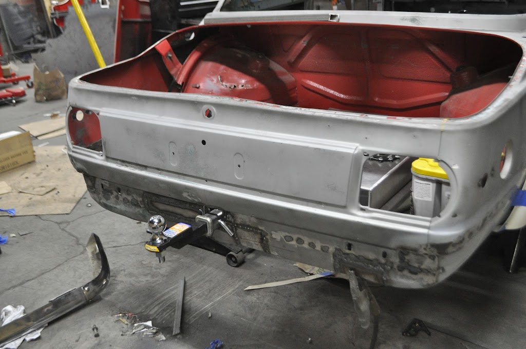
They still aren't that pretty, but for now they are rust free. After cleaning those I moved on to cutting the receiver to length. I forgot to take pictures while fitting it in place, but here it is tacked in place.
Here you can see the clearance between the body and the locking pin. It's tight, but shouldn't rub on the paint when installed.
Next up was to add the safety chain bars. When towing, the safety chains is used as a last resort in case the ball or hitch fail completely. It should keep the trailer from completely detaching until you can pull off to the side of the road.
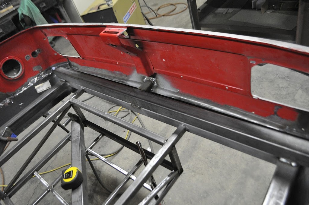
With those in place, it was time to reinforce the connections on the inside of the trunk. The picture below shows the receiver, the inner trunk frame, and a strengthening bar on top of both. The receiver is butted up against the trunk frame (you can't really see it, it's in the shadowed area underneath the top tube). The strengthening bar is to help keep the receiver from bending away from the trunk frame.All of these connections were welded fully around to ensure they won't fail.
Then I added another bar across the entire back of the trunk. This is to help keep the trunk frame tube from twisting in the center due to the moment from the tongue weight. The upper tube was notched to fit around the previously shown top brace. It will be stitch welded on both sides across the back of the trunk. The rear portion of the roll cage will tie into the far ends of this upper tube as well.
Here's a close up showing the notched area. Again, all edges are/will be fully welded.
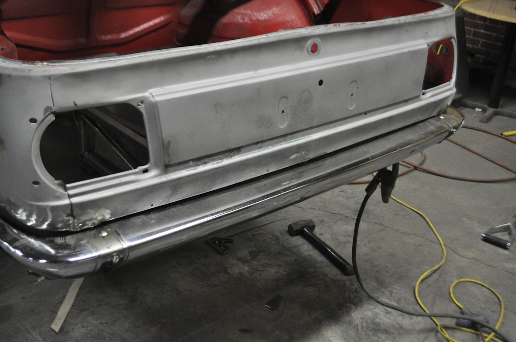
Now why did I need to clean up the bumper brackets for this little project you may wonder? Simple, so that I could ensure the entire hitch assembly would fit behind the stock bumper.
What hitch???
View from the bottom, it was very tight packaging. (For reference, the bottom edge of the bumper is in the top of the picture.)
And this is waiting for me tomorrow:
A partial sheet of 11ga and anew sheet of 18ga sheet metal for the front end work.


Leave a comment: