Announcement

Collapse
No announcement yet.

Project Crowdmower : Ford Chassis, Chevy Motor, and Nissan Transmission

Collapse
X
 
  • Filter
  • Time
  • Show
Clear All
new posts

  • laextreme5
    replied
    Its time to get this motor mounted finally. Over the past several weeks I've been chipping away at whats necessary to get her hung on her own. My garage being directly across the hall from my sons room really hinders how long and when I can work in the garage from a noise stand point. But irregardless im able to make progress.


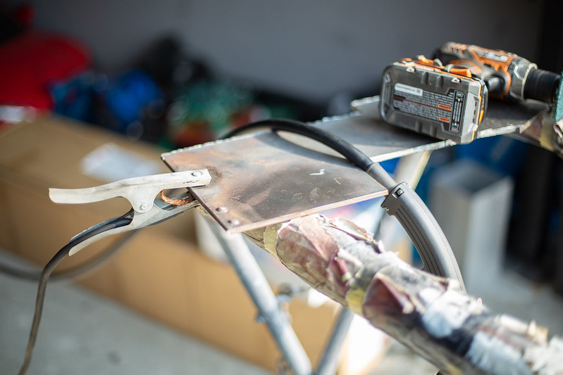
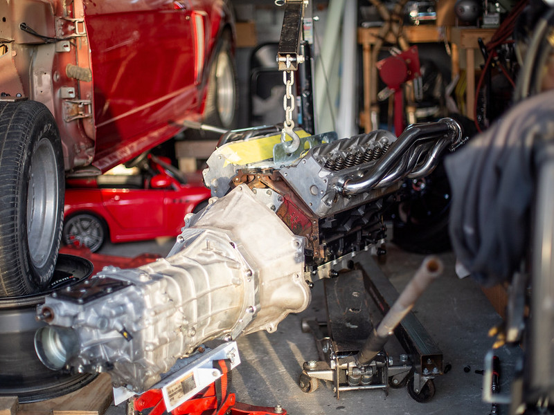
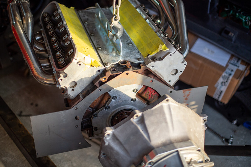
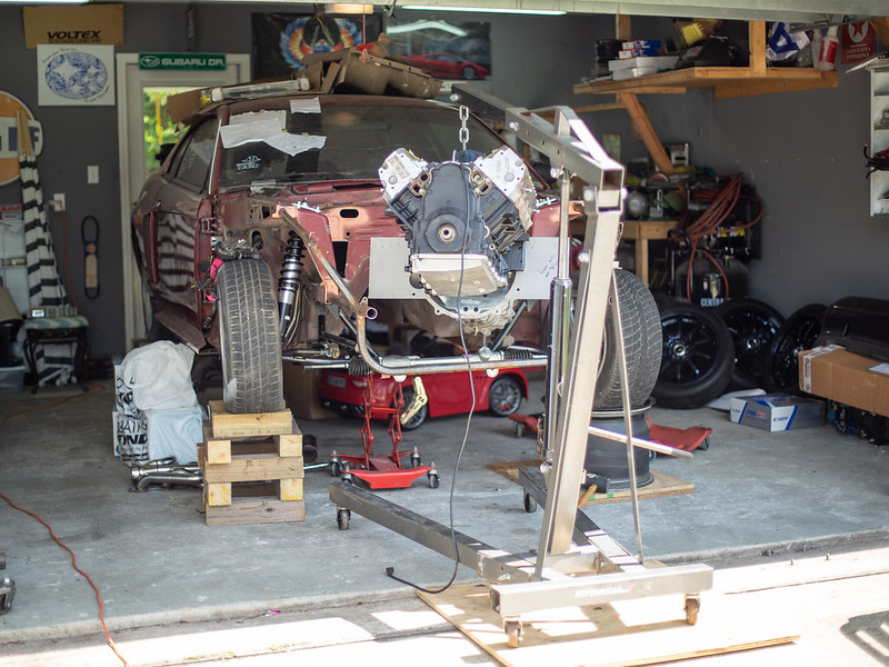
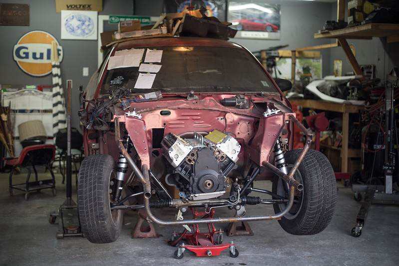
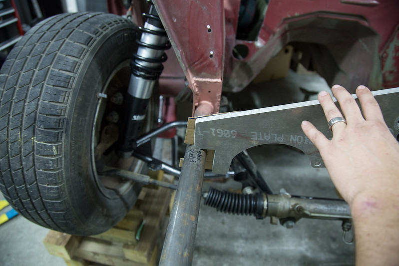
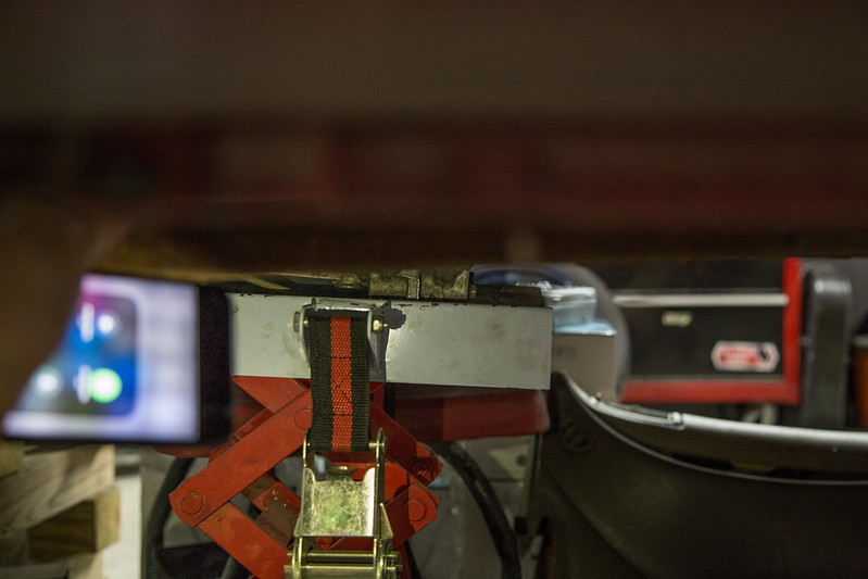
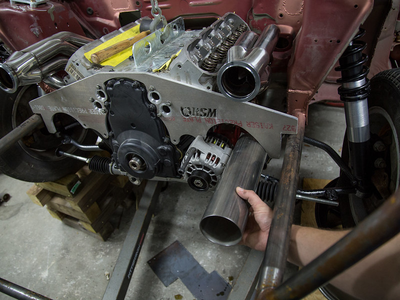
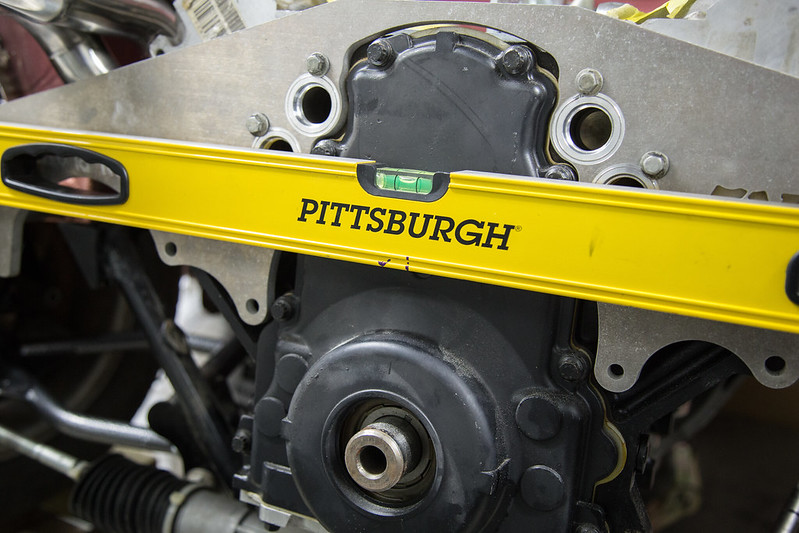
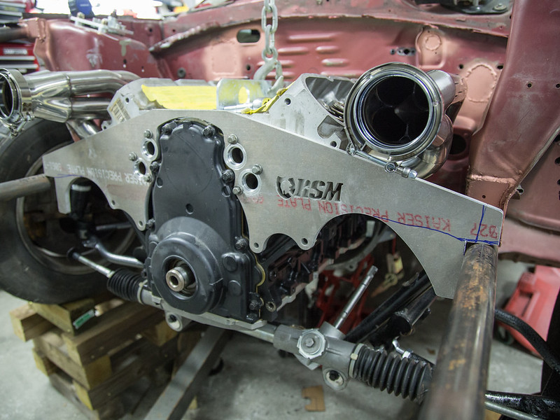
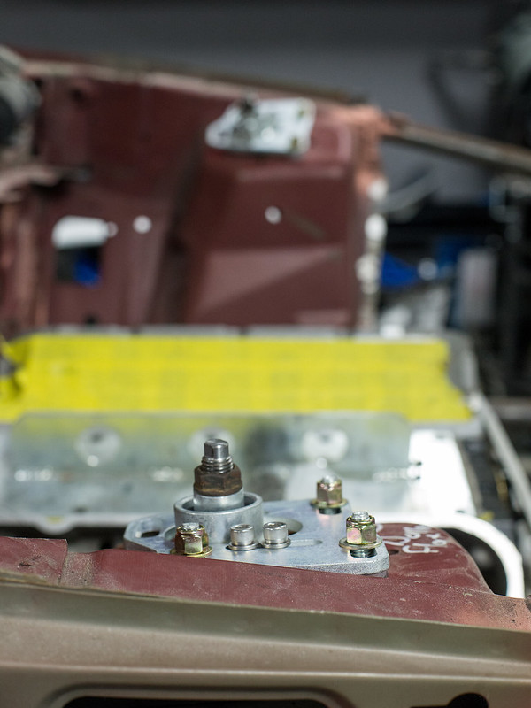
    Next step was to finalize mount tabs placement and drill all the holes on the tabs and the motor plate itself.


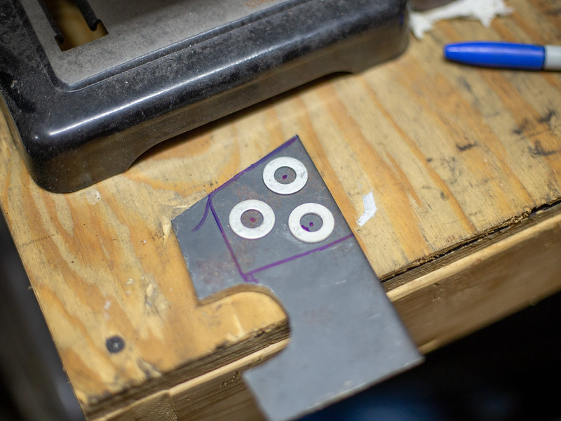
    IMG_0724 by lawrx, on Flickr


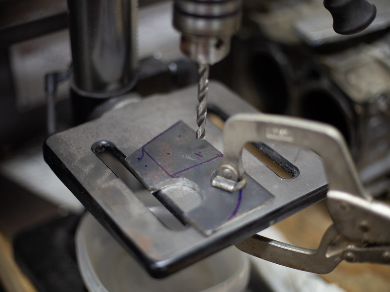
    IMG_0725 by lawrx, on Flickr


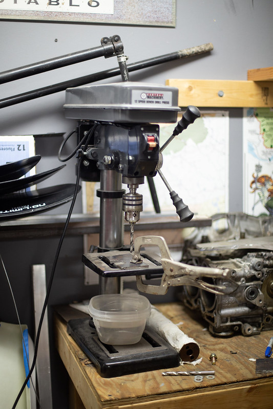
    IMG_0726 by lawrx, on Flickr


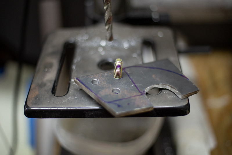
    IMG_0728 by lawrx, on Flickr


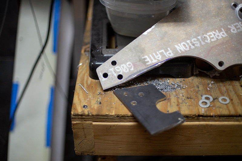
    IMG_0729 by lawrx, on Flickr


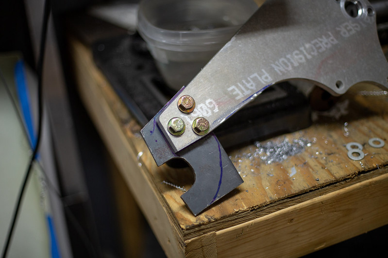
    IMG_0730 by lawrx, on Flickr


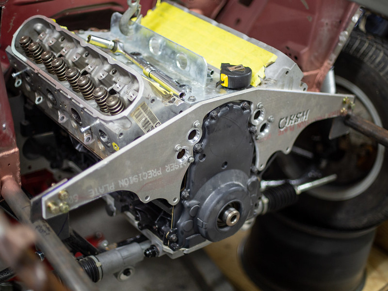
    IMG_0733 by lawrx, on Flickr


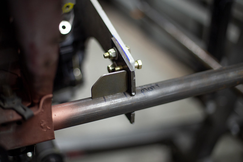
    IMG_0735 by lawrx, on Flickr


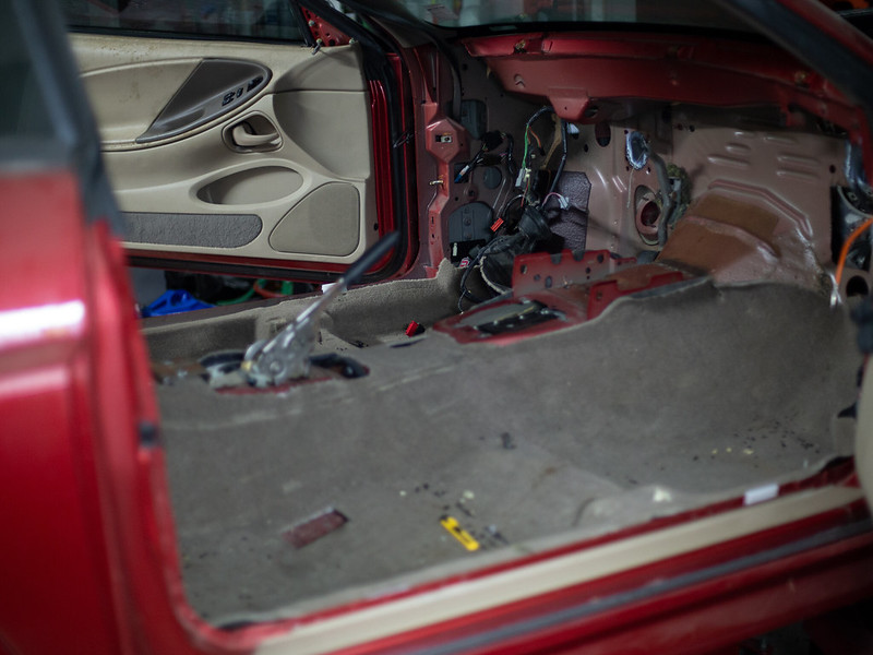
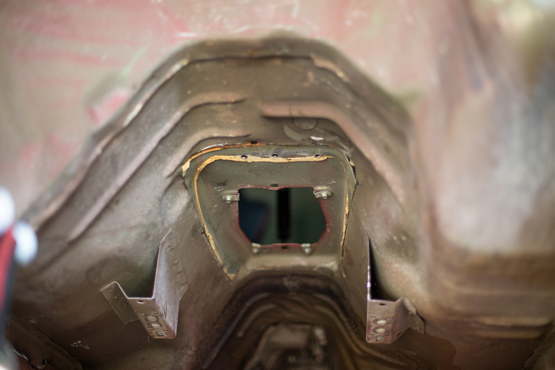
    One night I wasn't able to make much noise as my son was sleep and wife was already in bed and I was itching to do something on the car. I pulled out the seats to sell and the nasty carpet to throw out. I had a mouse/rat something that pissed and shit on it and it smelled. On top of ill be converting to a black interior regardless. This also gives me access to wire the car.


    IMG_0882 by lawrx, on Flickr


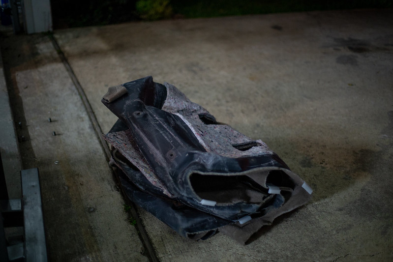
    IMG_0884 by lawrx, on Flickr
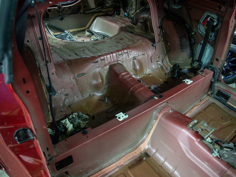


    IMG_0887 by lawrx, on Flickr


    IMG_0887 by lawrx, on Flickr


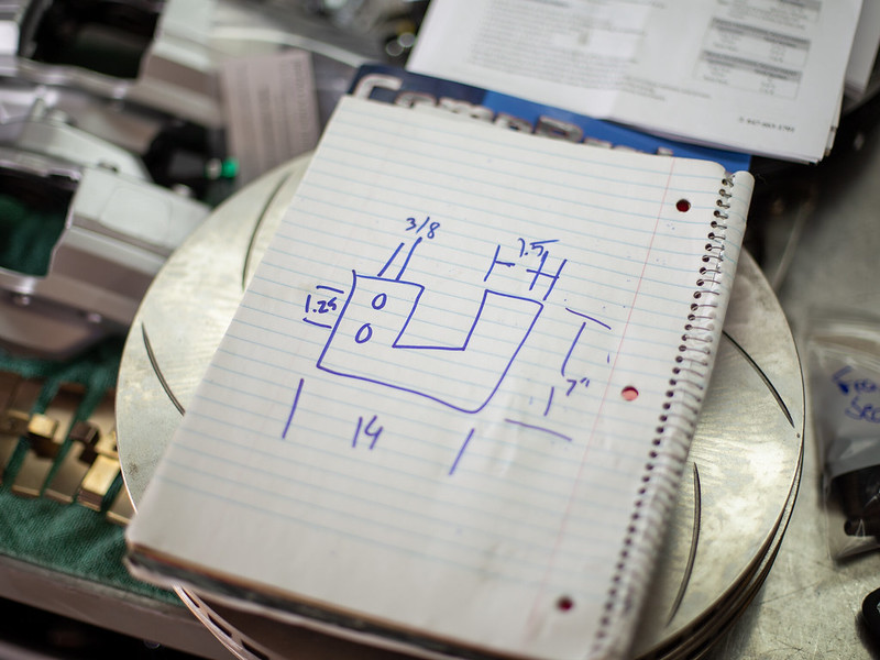
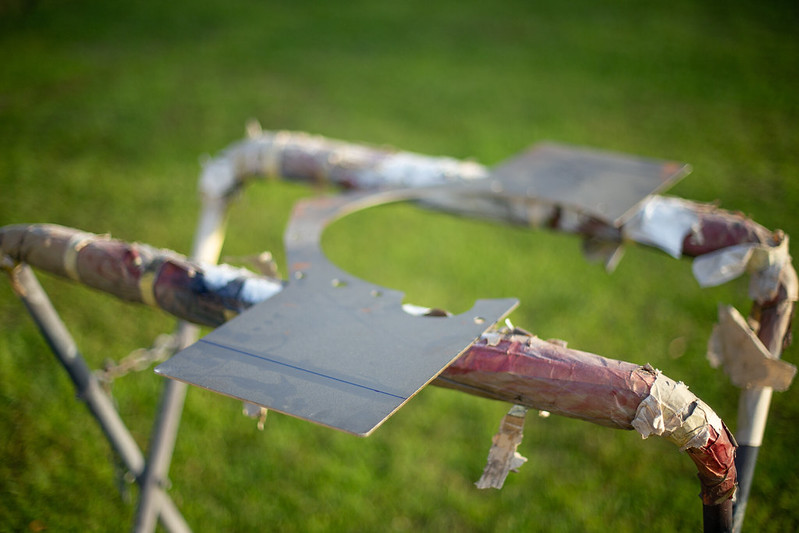
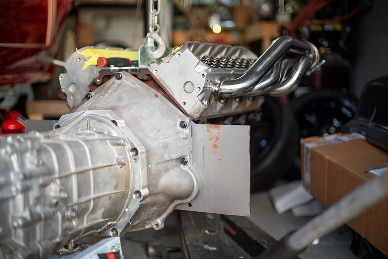
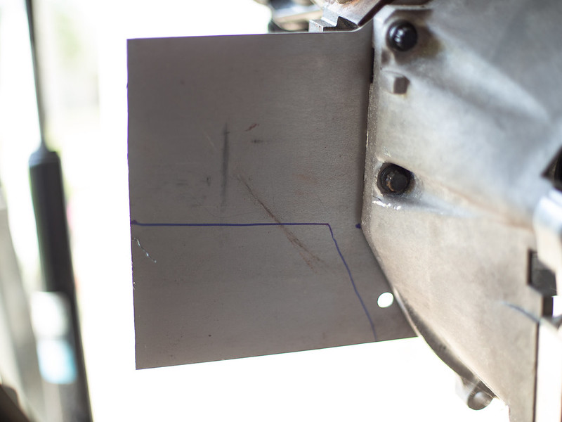
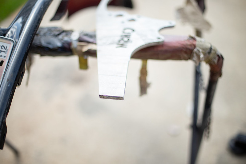
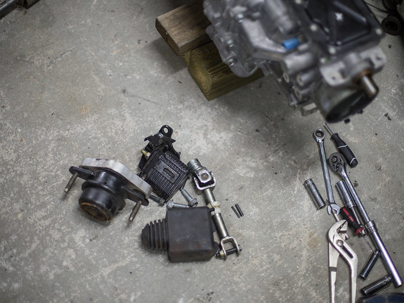
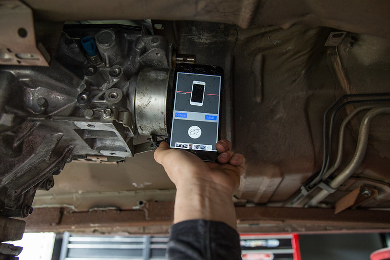
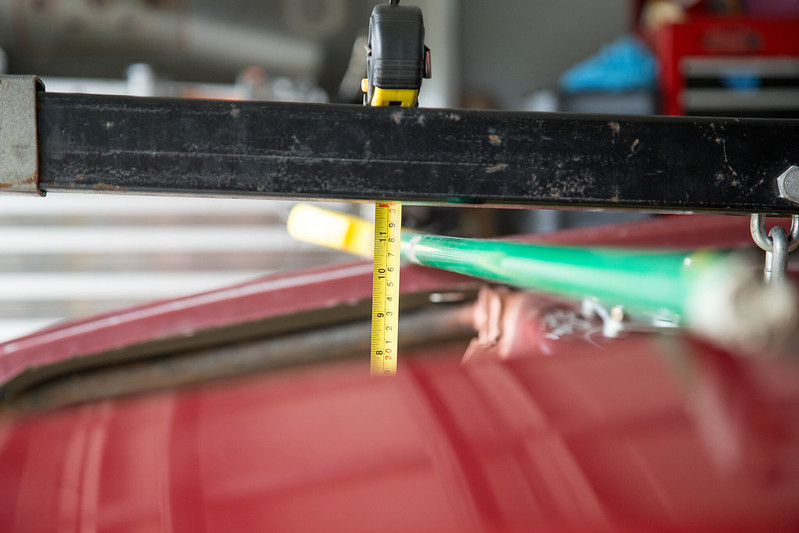
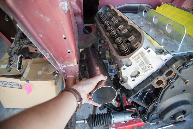
    Before welding in the front motor plate tabs I had to create a trans mount. Took some measurements and transferred them to some thick sheetmetal I had. This is only temporary, ill be getting a buddy of mine to whip one up in some billet t6b aluminum as the final product. For now this will do to place the motor and hold the trans up under its own weight.


    IMG_0888 by lawrx, on Flickr


    IMG_0893 by lawrx, on Flickr


    IMG_0895 by lawrx, on Flickr


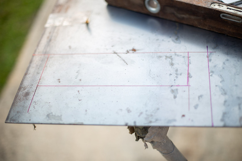
    IMG_0897 by lawrx, on Flickr


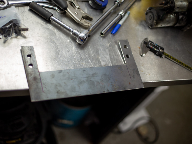
    IMG_0899 by lawrx, on Flickr


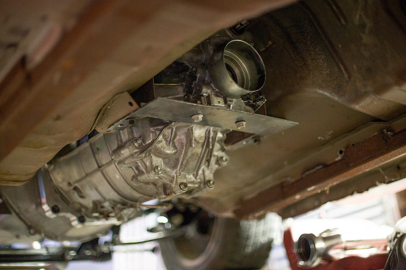
    IMG_0901 by lawrx, on Flickr


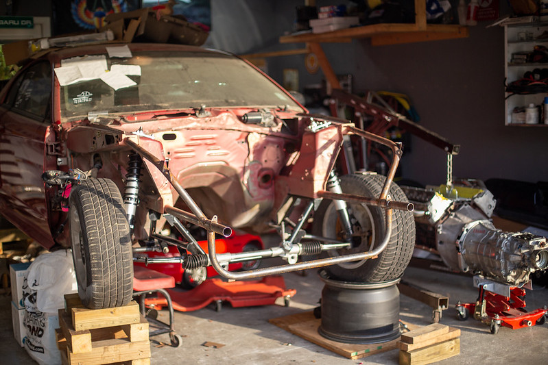
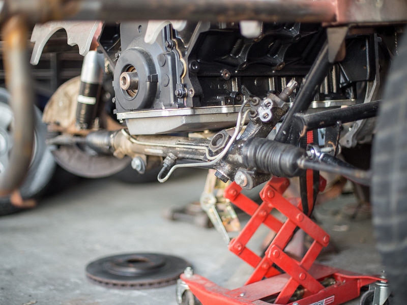
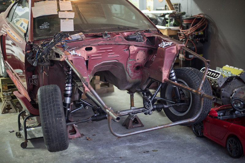
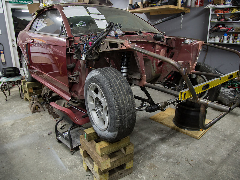
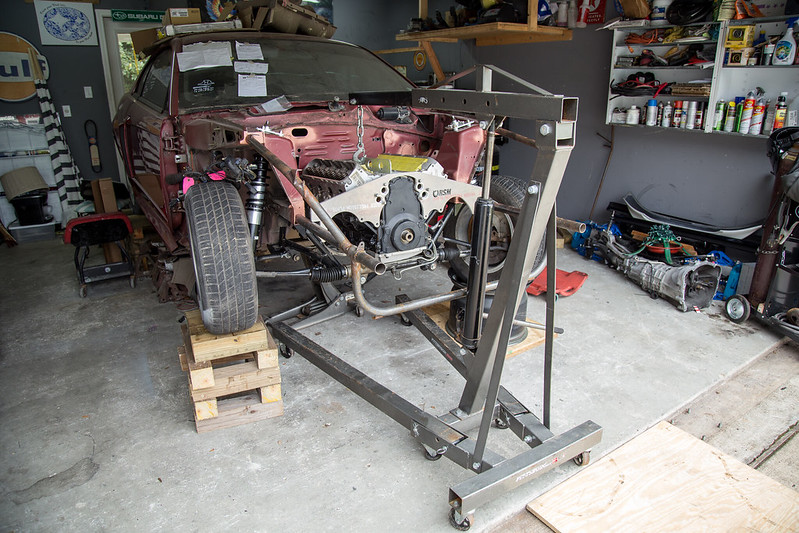
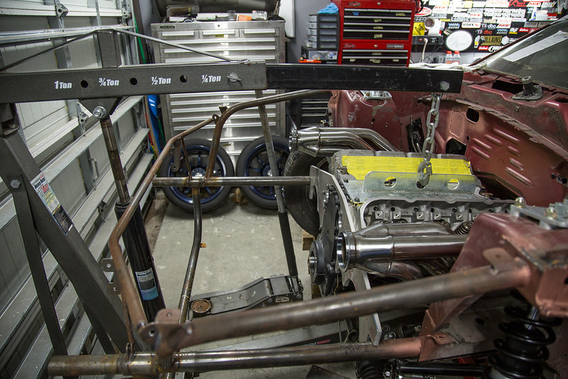
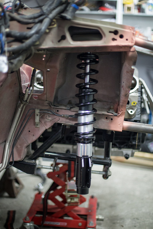
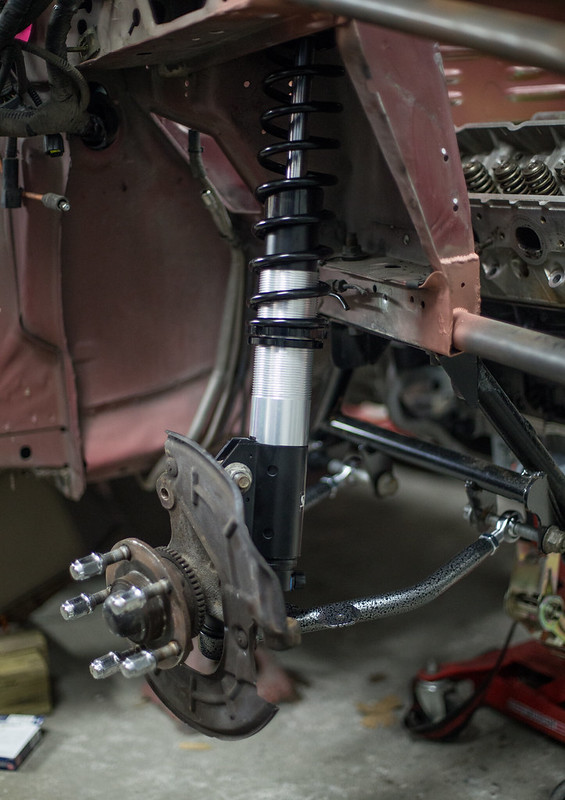
    With the trans mounted the last step was welding the mount tabs to the chassis.Through some test welds on my base material I used for the mounts and the welded the tabs up. With the motor fully suspending itself under its own weight I could set the car down on the chassis and off the stands. Had to clear out a bunch of stuff from underneath as over the last 6-8 months things had accumulated. Now that I had the motor mounted I also tested the front end to see clearance and space for the various objects that would take up space in the engine bay. Lots of room but there will also be lots of components.


    IMG_0902 by lawrx, on Flickr


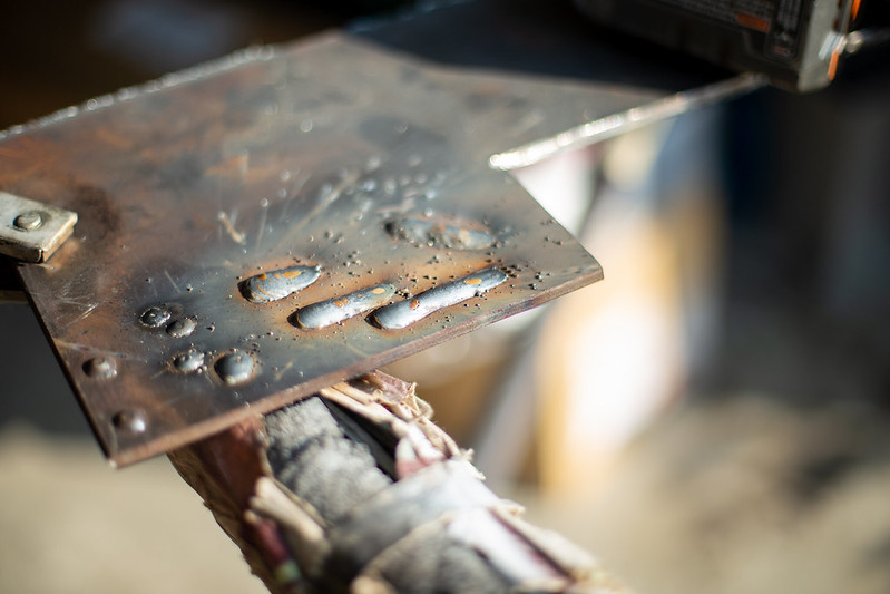
    IMG_0904 by lawrx, on Flickr


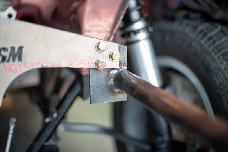
    IMG_0905 by lawrx, on Flickr


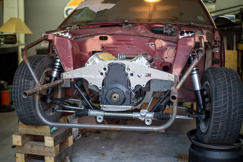
    IMG_0907 by lawrx, on Flickr


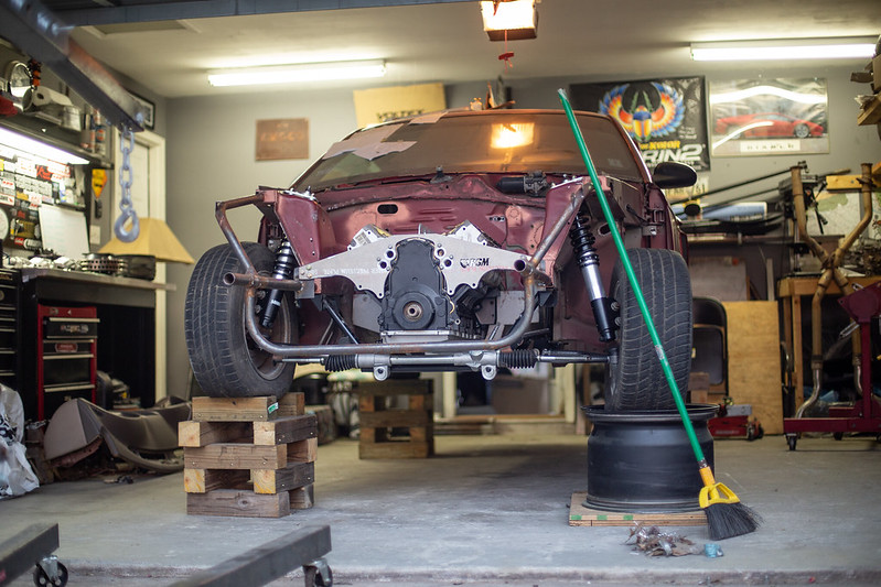
    IMG_0909 by lawrx, on Flickr


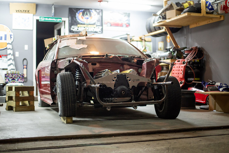
    IMG_0911 by lawrx, on Flickr


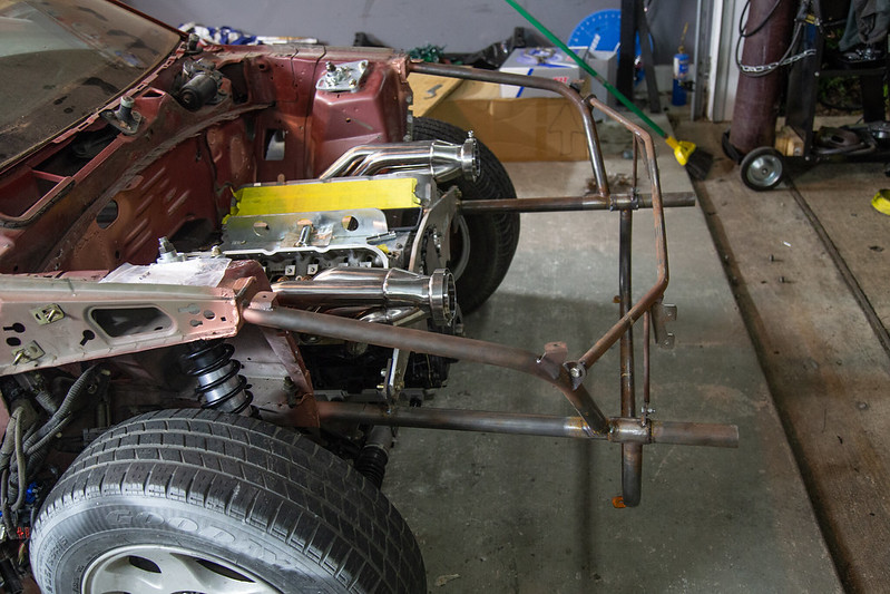
    IMG_0913 by lawrx, on Flickr


    IMG_0915 by lawrx, on Flickr


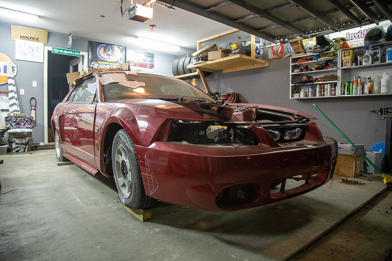
    IMG_0916 by lawrx, on Flickr


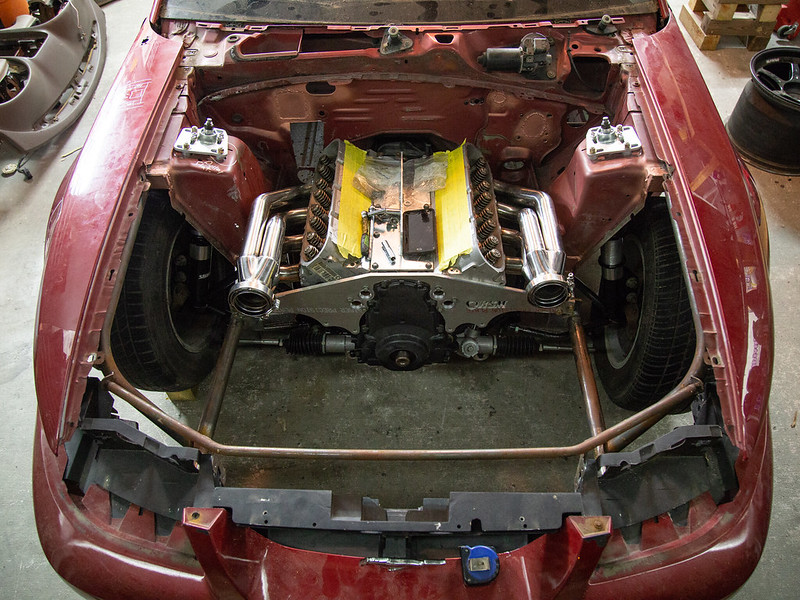
    IMG_0917 by lawrx, on Flickr


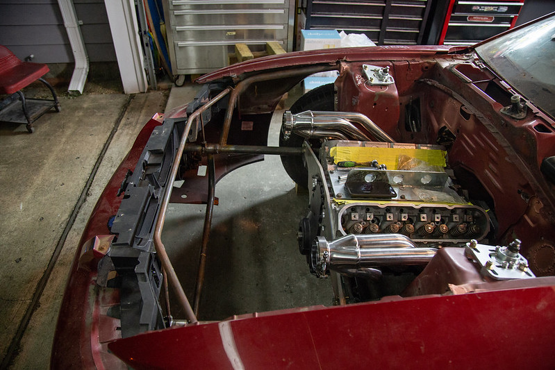
    IMG_0918 by lawrx, on Flickr

    Leave a comment:


  • laextreme5
    replied
    Originally posted by LCG View Post
    Don't you love when LS engines look tiny when installed "correctly" in a mustang?
    It should look neat and tidy with how i will be routing things. People underestimate how small they are.

    Leave a comment:


  • LCG
    replied
    Don't you love when LS engines look tiny when installed "correctly" in a mustang?

    Leave a comment:


  • laextreme5
    replied
    Originally posted by MikeyRa View Post
    It sounds and looks like you are going for some big power! Will you be fabbing up a belhousing shield or driveshaft hoop?
    Yeah, itll be up there. Initially i will run smallest wastegate presure i can get away with and a lowered redline until i grow into the power. Initial power will be in the 700-800whp range. As time moves on all in will be nearly double that.

    Bellhousing shield and driveshaft loop will come down the line as well as many other safety componets. Current focus is getting it up and running. to where its driveable. Then go from there. Cage is planned, battery cut-off, will have a fire extinguisher inside etc etc

    Leave a comment:


  • laextreme5
    replied
    Originally posted by toddzilla View Post
    Is there a reason you don't want to raise or enlarge the trans tunnel? I realize it's very easy for me to say "why not 'just' enlarge the tunnel?" but that seems like relatively easy task compared to some of the other work you're putting in here.
    Well. If i raise the tunnel , and therefore the back of the trans, i will remove the desired pinion angle i have achieved. Then i would have to raise the front of the motor to get back to my desired pinion angle. And im already cutting it close with hood clearance. Just really opens up a whole nother can of worms.

    Leave a comment:


  • MikeyRa
    replied
    It sounds and looks like you are going for some big power! Will you be fabbing up a belhousing shield or driveshaft hoop?

    Leave a comment:


  • toddzilla
    replied
    Is there a reason you don't want to raise or enlarge the trans tunnel? I realize it's very easy for me to say "why not 'just' enlarge the tunnel?" but that seems like relatively easy task compared to some of the other work you're putting in here.

    Leave a comment:


  • laextreme5
    replied
    Originally posted by baluzy36 View Post
    Looking great as usual!

    question about the motor plates, im assuming theyre used to reduce engine movement due to the high torque youll be producing? but are there no adverse effects from bolting directly to the chassis? i.e. no bushings
    They allow mounting of the motor virtually anywhere you like. The only adverse effects are increasing vibration through the chassis. Its really the only true way to mount a motor in high hp applications. typical motor mounts can fail and let a wild motor loose in the engine bay causing major failures. Also typical motor mounts can put alot of stress on the block at a few points. Where as a motorplate disperses that stress over more mounting points on the block reducing block distortion.

    Leave a comment:


  • baluzy36
    replied
    Looking great as usual!

    question about the motor plates, im assuming theyre used to reduce engine movement due to the high torque youll be producing? but are there no adverse effects from bolting directly to the chassis? i.e. no bushings

    Leave a comment:


  • laextreme5
    replied
    Pulled the motor back out to throw the midplate between the motor and trans. Roughly trimmed it up to see what else needed to be trimmed off. There should be enough room for the steering column to clear above it and down pipe underneath. Space is a lil tight with starter and frame space wise for downpipe to run through but will work out.

    Also had to remove some material from the trans tunnel to fit the big ole cd009. THis trans is quite deep. With trans 1/4'' away from top of tunnel there is still .5'' of trans sticking below lowest point of chassis. Going to have to fab some sort of protector plate for it. Also finalized trimming of the motor plate. Have one mount tab made for the driver side, just have to make the passenger side, drill the mount holes, then weld them on!


    IMG_0521 by lawrx, on Flickr


    IMG_0523 by lawrx, on Flickr


    IMG_0524 by lawrx, on Flickr


    IMG_0525 by lawrx, on Flickr


    IMG_0526 by lawrx, on Flickr


    IMG_0714 by lawrx, on Flickr


    IMG_0715 by lawrx, on Flickr


    IMG_0716 by lawrx, on Flickr


    IMG_0717 by lawrx, on Flickr


    IMG_0720 by lawrx, on Flickr


    IMG_0721 by lawrx, on Flickr

    Leave a comment:


  • laextreme5
    replied
    Originally posted by LCG View Post
    deemm.. that motorplate is thick...

    looking good mate
    I believe its 3/8" thick? Needs be for the planned horsepowers.

    Leave a comment:


  • LCG
    replied
    deemm.. that motorplate is thick...

    looking good mate

    Leave a comment:


  • laextreme5
    replied
    With the suspension mounted up im now able to set the motor position and get the mounts tabs fabbed up. I threw the old steering rack in loosely to hold the wheel halfway straight while I loaded the suspension and also to use as a baseline for oilman clearance. Also pulled the unnecessary linkage off the back of the trans as I will be using a forward mount shifter.

    Started with setting the motor in place and getting an idea on what the pinion angle was at in its rough position. The rear is currently sitting at 0* however I will be shooting for 1-2* once I get my adjustable arms in, so I just this amount to set the motor to. Was pretty damn close with my rough placement which made it easy for final adjustment. I stuck a (somewhat) straight edge across the fenders to measure for intake manifold clearance to verify I had plenty of room


    IMG_9621 by lawrx, on Flickr


    IMG_9624 by lawrx, on Flickr


    IMG_9625 by lawrx, on Flickr


    IMG_9754 by lawrx, on Flickr


    IMG_9755 by lawrx, on Flickr


    IMG_9758 by lawrx, on Flickr


    IMG_9760 by lawrx, on Flickr


    IMG_9762 by lawrx, on Flickr


    IMG_9764 by lawrx, on Flickr


    IMG_9765 by lawrx, on Flickr


    IMG_9801 by lawrx, on Flickr


    Ran out of time to make loud noises ( son went to sleep, his room is across the hall from the garage) so I decided to mock up some new manifolds I picked up. They are Speed Engineering. Fit is good. Quality is good. Don't really have any complaints considering the price of them. Also did some mock up with the alternator and 3.5'' tubing I had which will be the downpipes size off the turbos. Def room to make it work how I want with some motor plate trimming.


    IMG_9793 by lawrx, on Flickr


    IMG_9795 by lawrx, on Flickr


    IMG_9797 by lawrx, on Flickr


    IMG_9798 by lawrx, on Flickr


    IMG_9799 by lawrx, on Flickr


    IMG_9800 by lawrx, on Flickr


    IMG_9802 by lawrx, on Flickr

    Leave a comment:


  • laextreme5
    replied
    Got the front suspension I and mounted
    -Strange 10 way front struts
    -TeamZ camber/castor plates
    -TeamZ lower front control arms
    -TeamZ coiler kit


    Few word about everything. Shocks and coiler kit fit great. No fuss getting it together and installed.

    Camber/castor plates have TONS of adjustment. And I could mod the strut tower hole and get even more adjustment out of them if I wanted to. Cant have too much adjustment.

    And the lower control arms. Bit disappointed in them. Spacers for the bolts where it connects to the control arm are slightly too small and need to be reemed out to fit. Balljoint boot on one of them doesn't want to stay down, will have to find a way to keep it attacked to prevent grime and dirt from getting in there.

    IMG_9605 by lawrx, on Flickr


    IMG_9606 by lawrx, on Flickr


    IMG_9607 by lawrx, on Flickr


    IMG_9608 by lawrx, on Flickr


    IMG_9609 by lawrx, on Flickr


    IMG_9610 by lawrx, on Flickr


    IMG_9611 by lawrx, on Flickr


    IMG_9614 by lawrx, on Flickr

    Leave a comment:


  • laextreme5
    replied
    Doing a bit more thinking/measuring/eyeballing.

    Its looking like how I want to route thinks just wasn't going to work with a big single. I couldn't find headers to sit where I wanted with the motor sitting as low as needed to fit the intercooler/intake setup I wanted.

    Drew out an idea on the fender for a twin turbo setup. Id originally wanted to run a low pro hood, exhaust out the back etc to give it a more "sleeper" low profile attitude. going twin turbo vs big single with shorter intake would allow that. I still want proper ducting for front airflow and I feel this would work well.

    Also did some mock up with some 3.5'' tubing and theres ample room to run a downpipe down each side with the block with the manifolds I want to run. Also issue I have is steering shaft. It will be right in the way, however I can shorten the output from the steering rack and use some custom joints to move it over slightly for exhaust routing.


    After taking al this into account I was able to put the motor where I wanted in reference to the chassis while sitting on my trans jack. Soon I wil be ordering the front suspension to set the chassis level and motor will be ready to be placed accordingly and bolted up via motor plates in its permanent position.


    IMG_9184 by lawrx, on Flickr


    IMG_9185 by lawrx, on Flickr


    IMG_9187 by lawrx, on Flickr


    IMG_9189 by lawrx, on Flickr


    IMG_9190 by lawrx, on Flickr


    IMG_9191 by lawrx, on Flickr

    Leave a comment:

Working...
X