Originally posted by Miroteknik
View Post
-
Trying to make sure that I make my SEMA Convention deadline for completion, while still having time before that to Test and Abuse the car, with enough time to do all the final fitment and cleaning for the show after the abuse.. LOL -
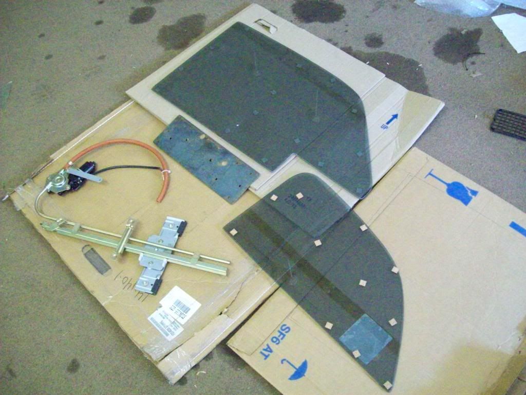
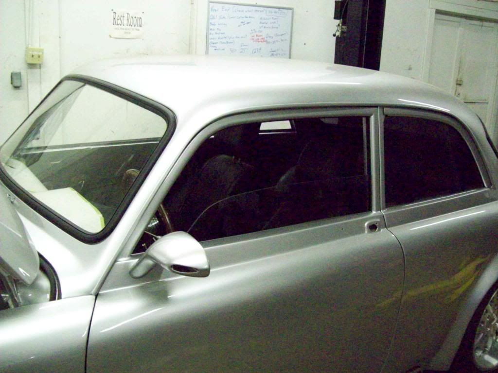
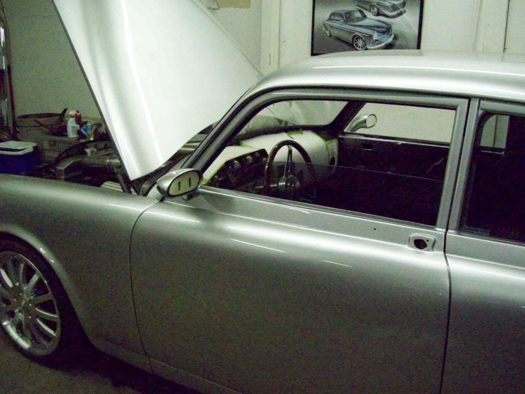
Here are some pics of the One Piece Door Glass and Power Window Conversion kit, and it came out pretty nice.. I went with a very light smoke glass instead of a clear, but you can still clearly see in the car.
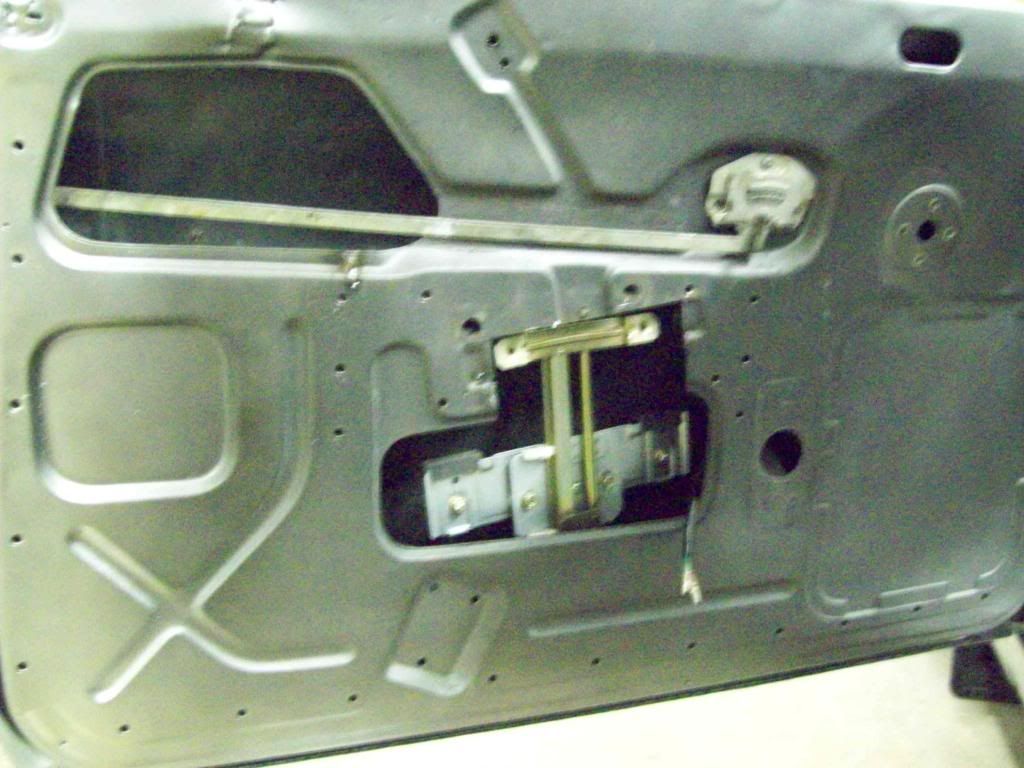
Here is a pic of the basic kit that I have come up with for the build cars, and I even have a full replacement window felt and belt line kit to work with the original door and channels. There is a plate in the kit picture, and that plate allows you to install the new regulator assembly, and keep the original arm rest location, without losing any strength.
You can also see the glass I had made to delete the pop out rear quarter window, and make it a fixed glass instead. Some may not like that option, but the pop out window's apprearance really throws out the styling on these cars, because it doesnt match anything.
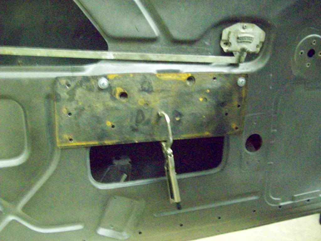
Here are some basic install pictures, and it really isnt that bad, eventhough there is a bit of cutting. When you remove the factory vent window, there is a mount piece in the window opening that will need to be removed, but it is very easy to do even if the vehicle is painted. You will also have to remove the factory window cable roller brackets from the inner door, but you can drill out the spot welds from the outer(Interior) door shell, and then they will come right out.. The only real cut after that, is the notch cut for the Power Window regulator mount to clear, and it is a very non evasive cut also.
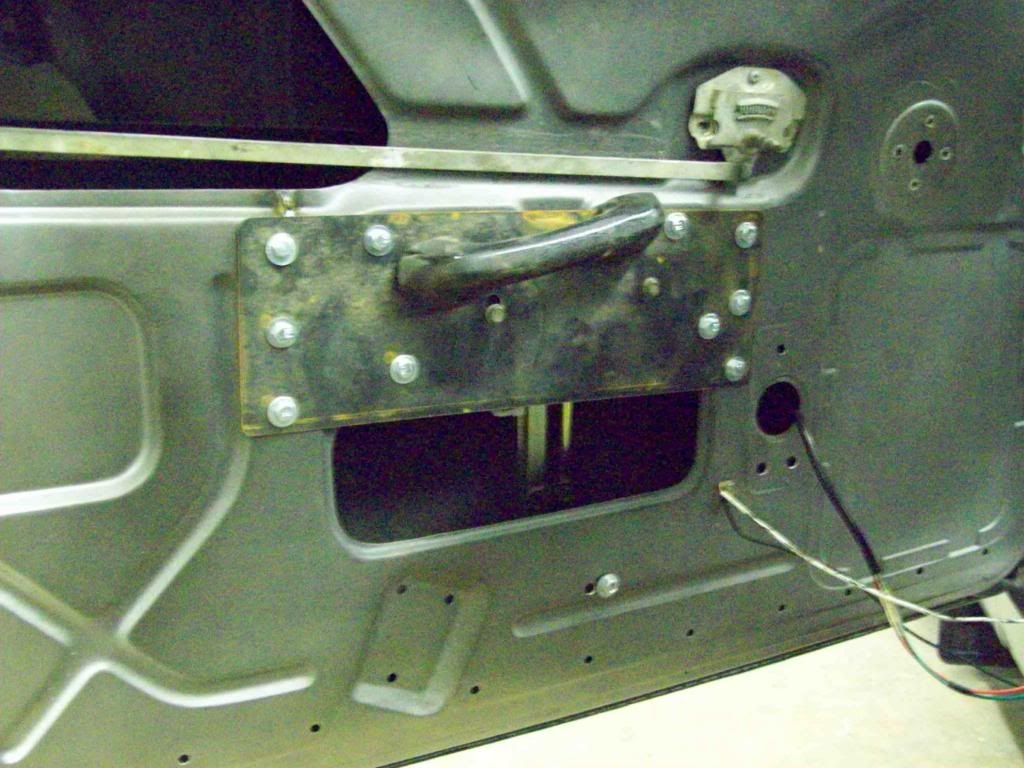
When fitting the plate, I will normally put it in position for drilling while on the door, and the position is dictated by some reference points on the door shell. After you have it in position, you can then drill out all the mount holes, and I like to drop a bolt in each hole after it is drilled, so there isnt any chance of getting out of line with the other holes. I have alot more bolt holes than are necessary, but I wanted to be sure to actually brace the door, rather than make it flimsy with this modification.
After all my holes are drilled, you can then easily mark where the notching cuts need to be done, and those are also determined by the door shell stamping features, so it is very easy not to make a mistake.
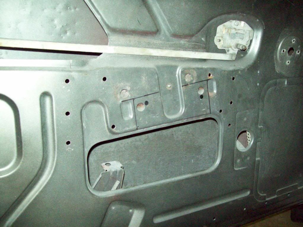
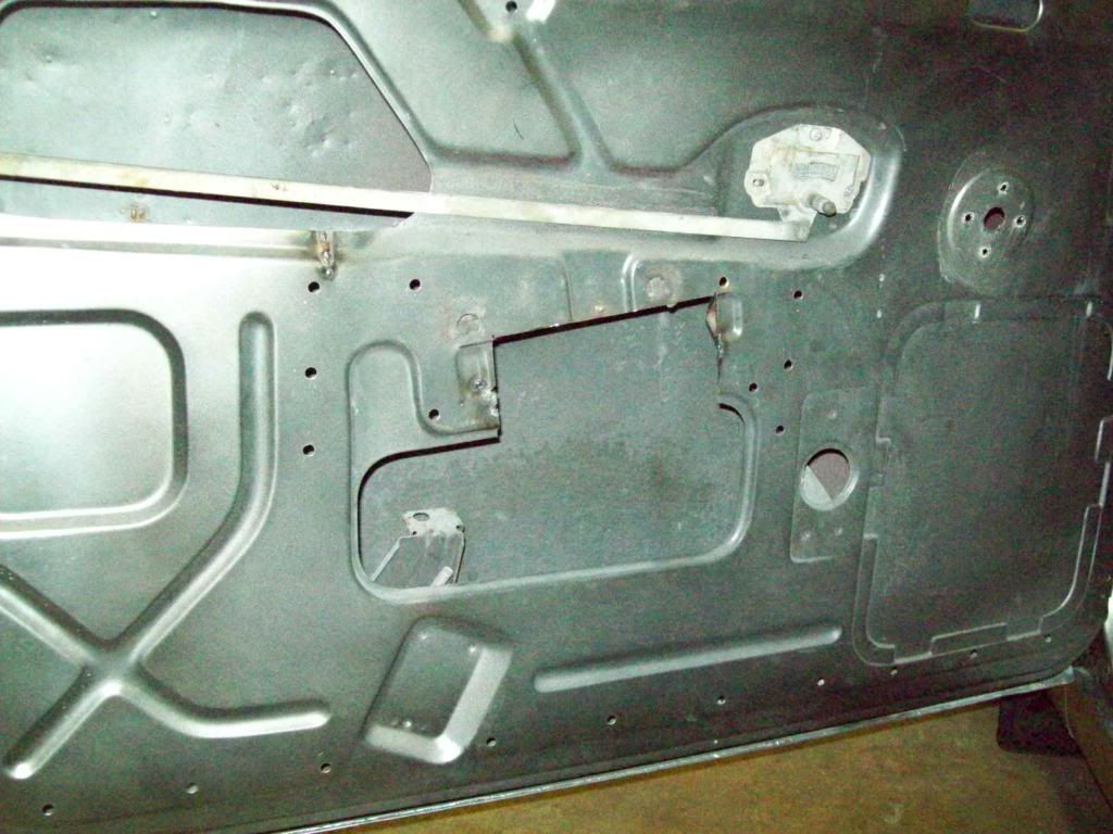
After you have that done, the regulator will have room for access, and then you can put it in place.. After it is roughly mounted, you can then mark for the two more drill holes that are used for the window motor support bracket, along with the lower regulator Adjustment bolt.. You need to have the lower adjustment bolt, so you can adjust the pitch of your window, as it moves up and down, so it will be on the same plane as the door frame. That adjustment is just a matter of adjusting a nut on the back side of the door shell, and that will hold the bottom regulator in the correct pitch
Here is the fitment of the new glass, along with the new weatherstripping, and it looks much cleaner than the bulky Oem rubbers and flaps.
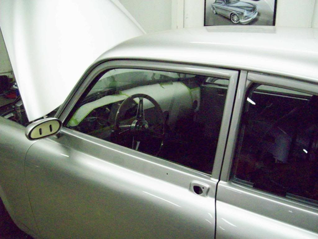
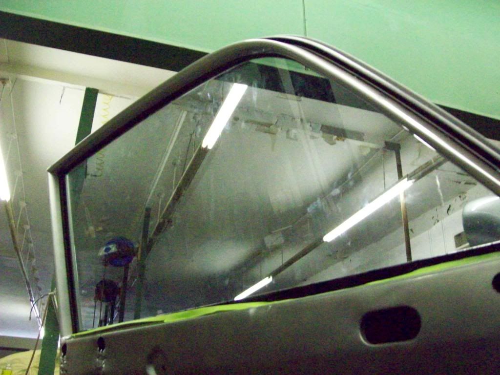
OEM Comparison Pic..
Leave a comment:
-
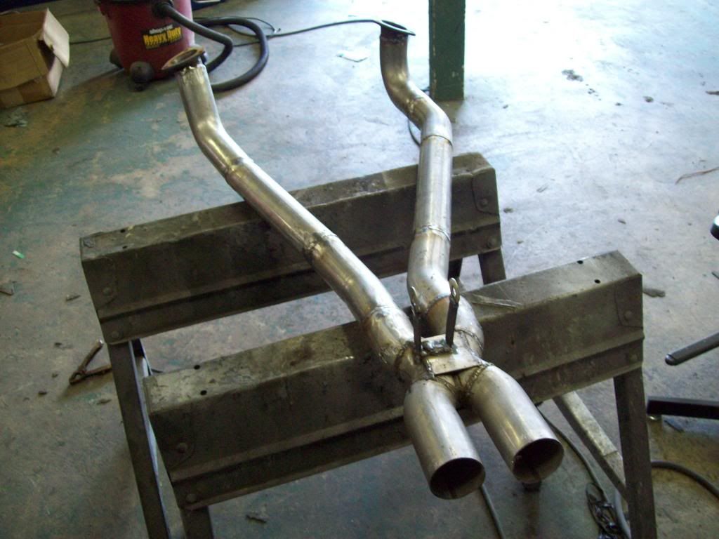
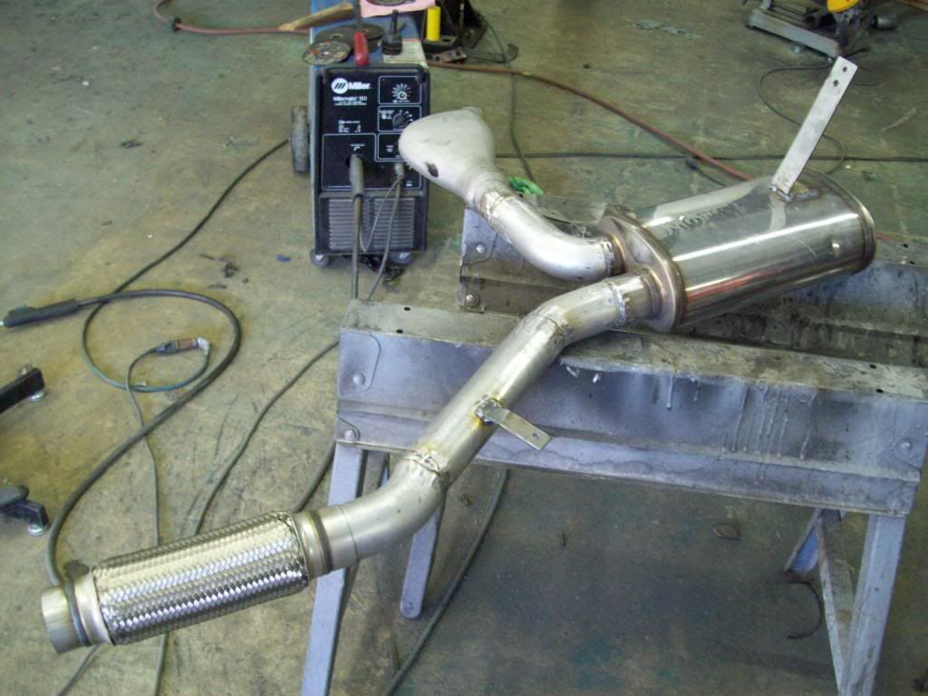
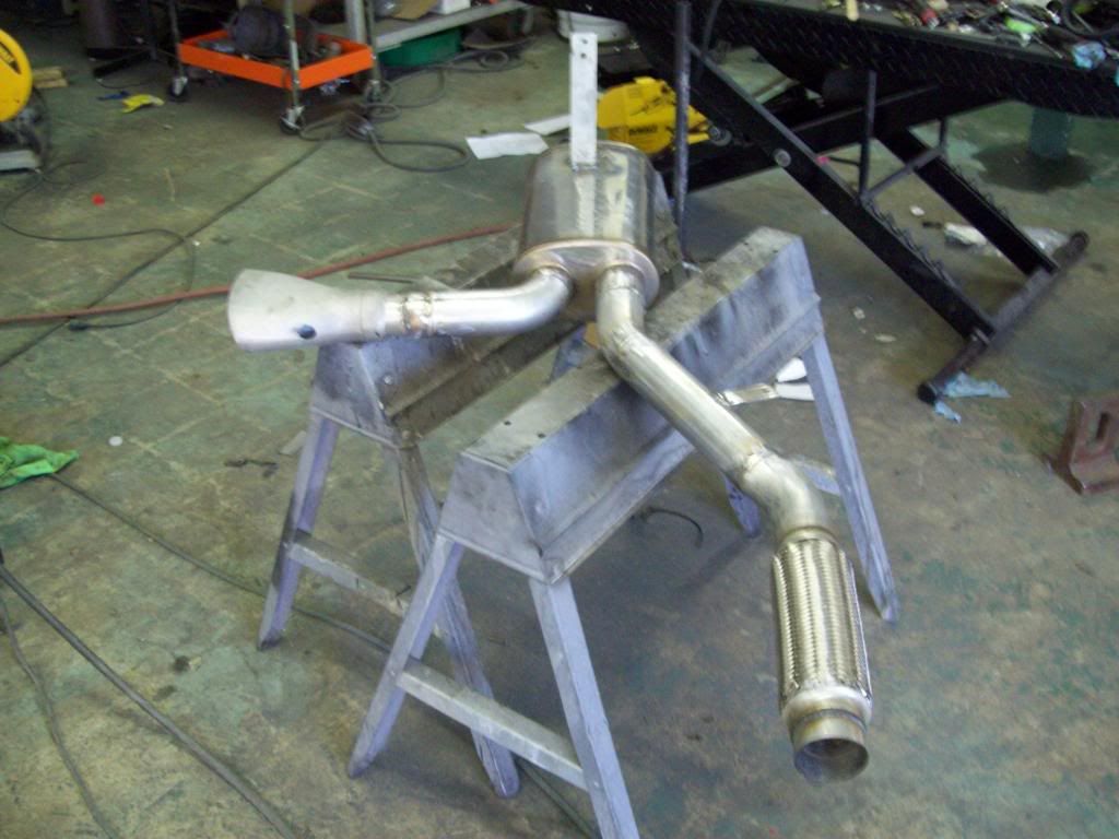
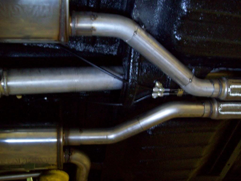
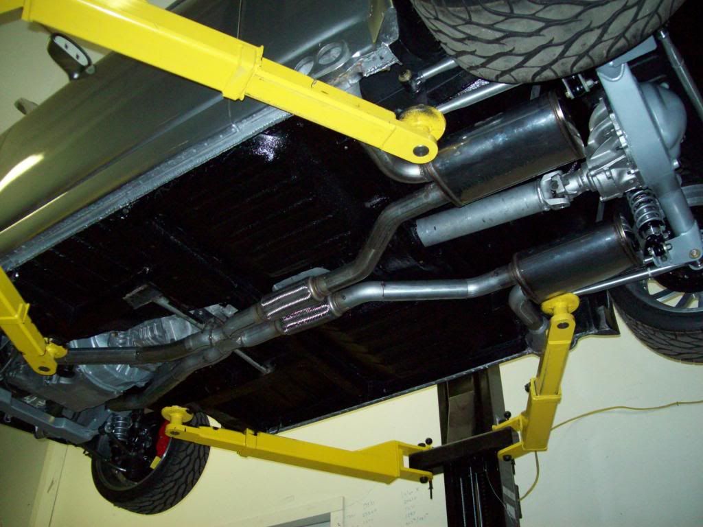
Got the exhaust finish welded up, minus the O2 sensor bungs, but I will do that when I remove the exhaust for coating. At that time I will do the rest of the finish grinding and final touches before the hot coating, and then it should look alot more respectable. I will be coating the whole exhaust unit (Including the Mufflers) in the same Silver/Chrome color my header kit is in, but that will be minuse the actual woven stainless area of the center flex joint.
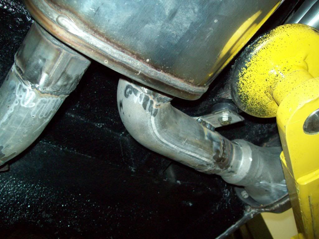
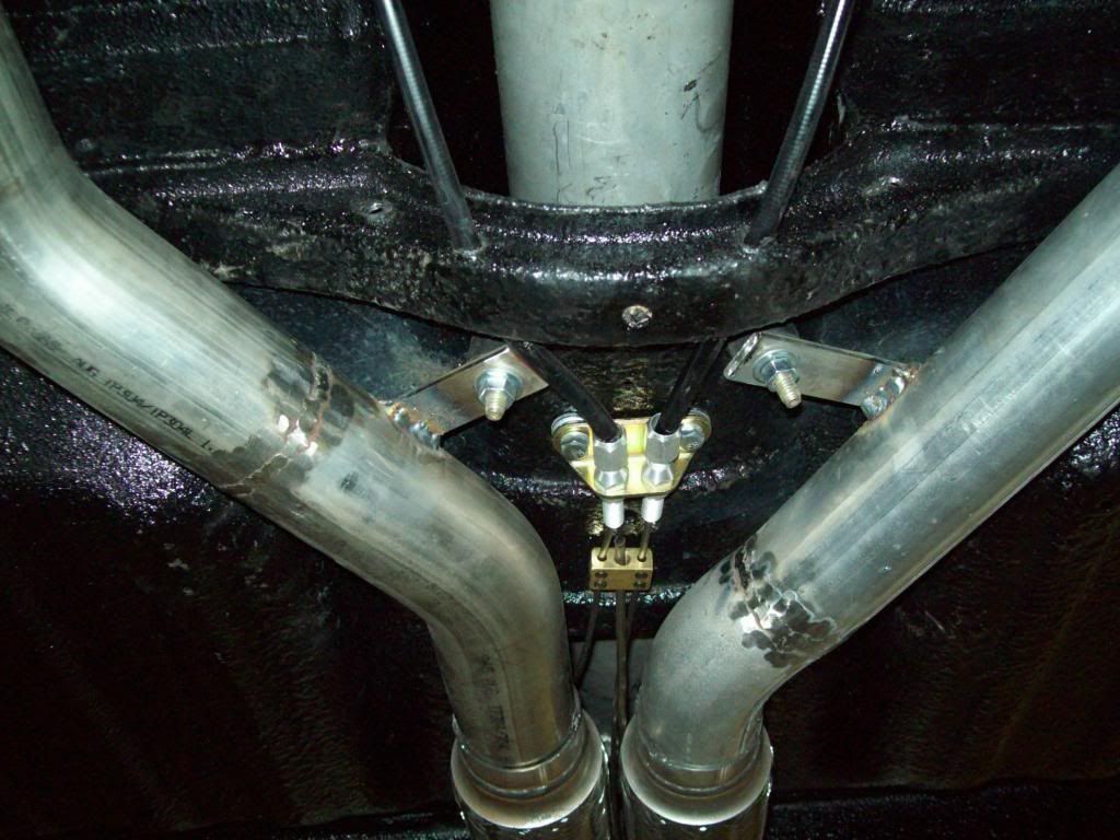
The exhaust fits pretty tightly to the body, and there should still be enough room of engine load and torque, but the rear section after the X-Pipe will be very solidly Mounted, so I can avoid exhaut tip/body rattle. With the performance engine mounting setup, the motor will be held fairly tightly, so the stainless mesh flex joints should be able to absorb most of the movement needed. It has been years since I have actually made my own exhaust, but I really think this will be nicer than anything I could have gotten done in my area, because the Mufflers are within an 1/8 in being exact in front/rear postion, side position, and front/rear height and angle, which is something that can really kick your ass trying to get done. I actually had to make the right and left side of the front/center part of the exhaust just a bit off of each other for Starter Clearance and the off center Volvo emergency brake lever, but I tried to make it look like a very similar overall setup anyway.
The front/center section of the exhaust is held in place by the Header/Collector mount, and with pin bolt setup that attaches to the transmission tail housing, so it is very solid.. The motor and tranmission move the same during engine torque, so you can actually attach the exhaust to the transmission with no real issue at all. The rear section right after the X-pipe and flex joints, has a hard rubber mounting that attaches through the drive shaft tunnel, and that offered and easy and rigid attachement point. The mufflers are attached to the rear interior compartment walls by a heavy strap that was welded to the muffler, and it is nut and bolted through the body with a rubber insulator also. The tail pipe section off the muffler, has a rigid bracket welded to it, and that allows that section to be attached to the body structure with a bolt/nut and insulator also. I think there is enough rigidity and flex in the way I have it all setup, but I guess I will have to see if changes need to be made after the car fires up and moves around.


Leave a comment:
-
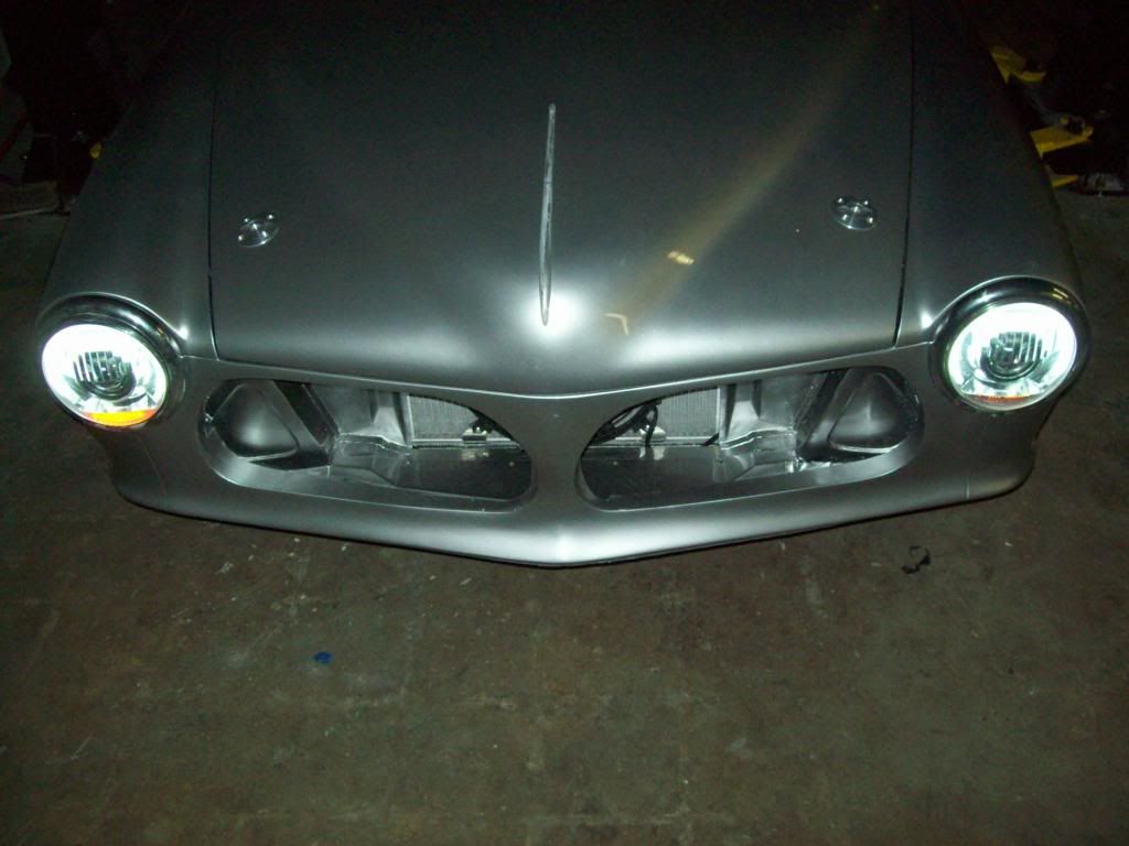
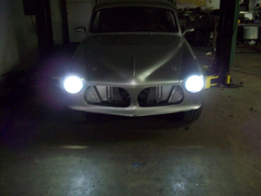
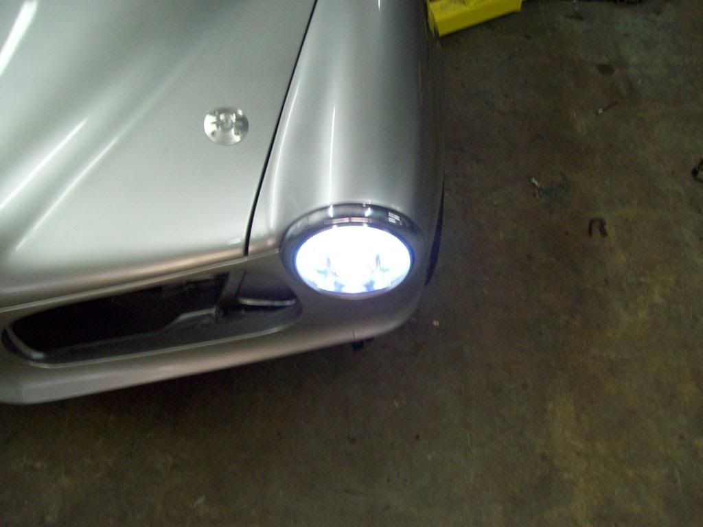
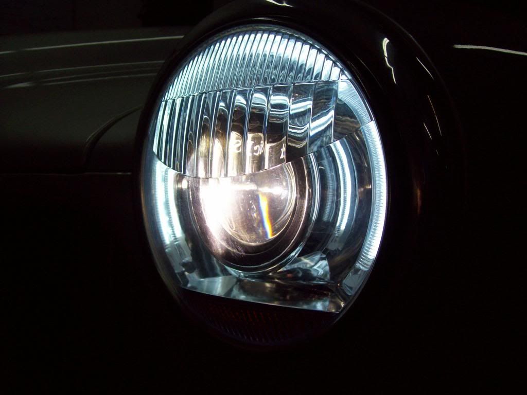
It appears we now have the first sign of Life.. LOL Working out the wiring, and I figured I would start with the Custom Headlights right now, because I am waiting on a few items to fire the motor up. I tried to capture alot of what is going on with the headlights, but there is a glare that I cant get rid of in most of the pics, but there is alot more definition of the LED Halo Components and Projector Eyeball in person.
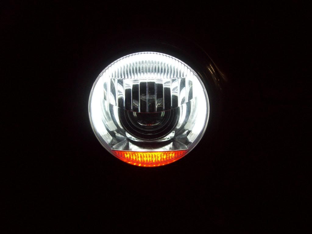
Here are just the Daytime Halo's operating, along with the Right Turn Signal.
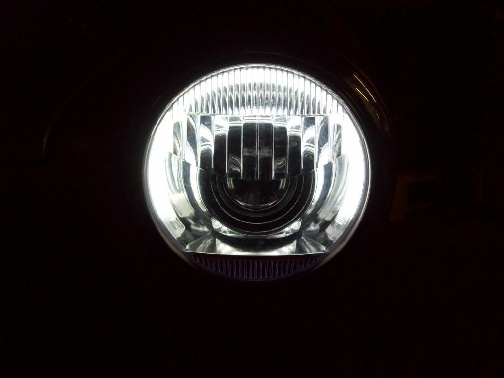
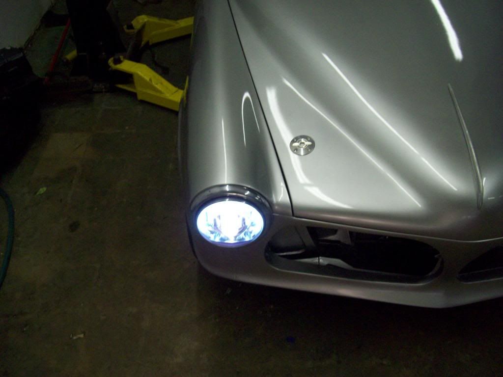
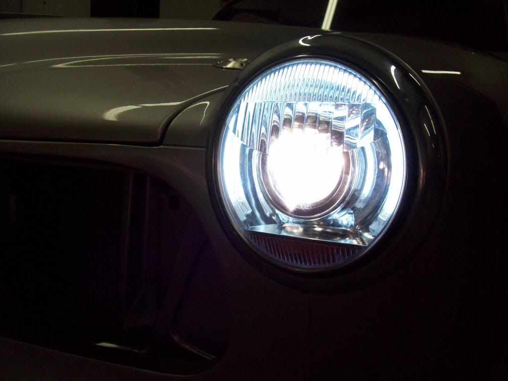
Here are the Low Beam lights on, because if I kick the brights on, there is way too much glare.. These lights are Crystal Clear in person, and I dont know how to describe other than, the light is very Crisp and Clear. The last three pictures are a better representative of how the lights appear in person with out the glare from the pics being taken head on, and that is how they look if you are standing directly in front of the car in person.

Leave a comment:
-
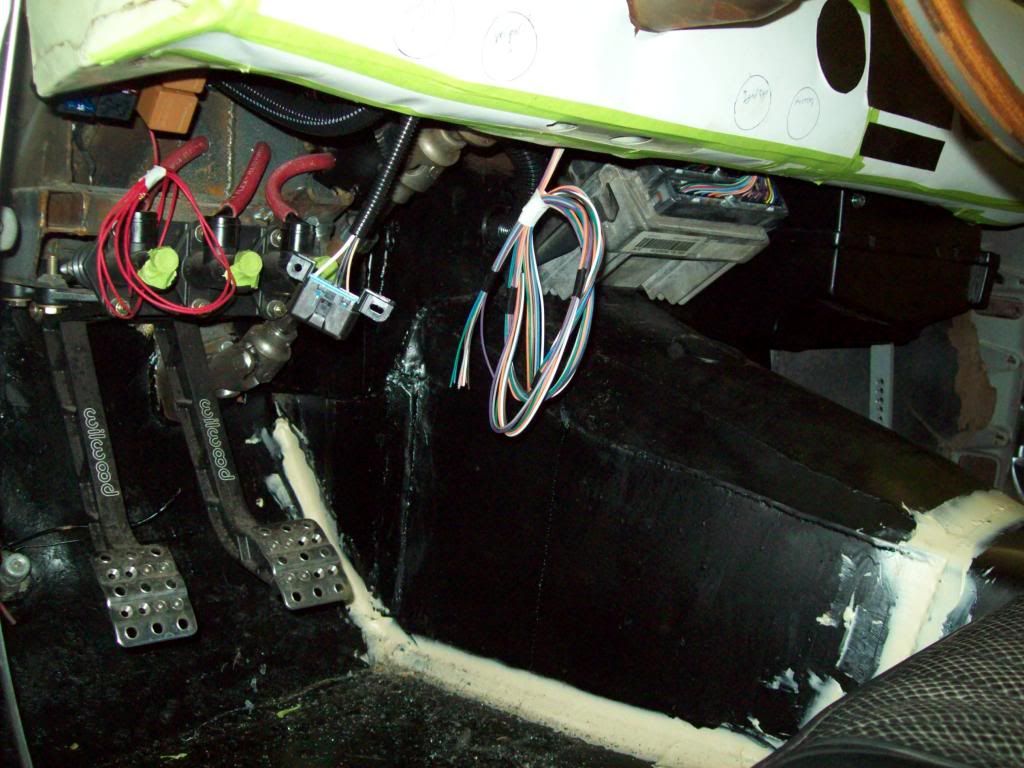
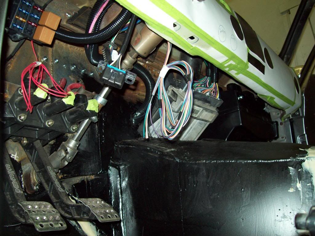
Here are some pictures of the computer mounted under the dash, along with the engine management fuse block, and hopefully some of the guys who are unfamilar with the LS transplants can actually see how simple it is. The loop of wires you see still hanging, are my guage signal and warning light wiring, and it blends very nicely into upgraded electronic guages. You can also see the Data Link Connector (DLC) hanging down, and there is enough length to pretty well mount that anywhere I would like to hide it, but I am still deciding where I would like to put it.
The next stages are to coat the inner firewall with the same chassis paint as I have done the rest of the intererior , and then complete the final insulating of the firewall the rest of the interior. The Body Wiring Harness is really just as simple, and will be added once the painting and insulation is completed. I have ordered the AC/Heat Assembly, and will have it ready to mount after the rest is done, but you can see that it is actually a pretty decent fit now. For modern air conditioning, the dash really needed to be made to hang down further, and now I am happy with the outcome there, because its exposure below the dash is pretty well standard to most conventional cars today.
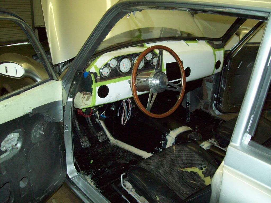
Hopefully the last pictures show the perspective of normal standing with the door open, and the fact that you cannot see the Computer Mounting or wiring, because all the other pics were taken while sitting on shop floor to get an under dash angle for viewing.


Leave a comment:
-
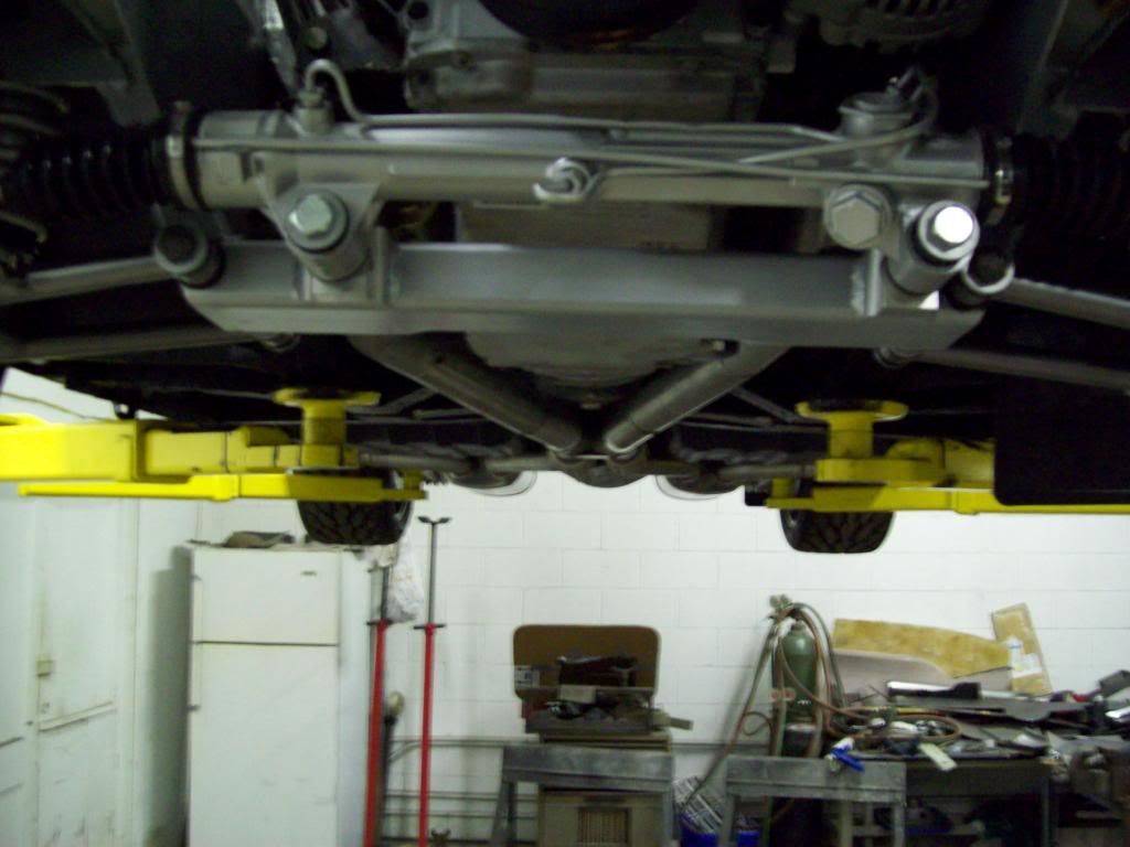
I was able to make the original Emergency Brake setup work with the Wilwood cable setup and the exhaust setup, so I dont have to worry about relocating the oem emergency brake lever. I actually like the original location of the brake lever, so I wanted to do what I could do to keep it there, and not have to go through the extra work of modifying something else to replace it.

Leave a comment:
-
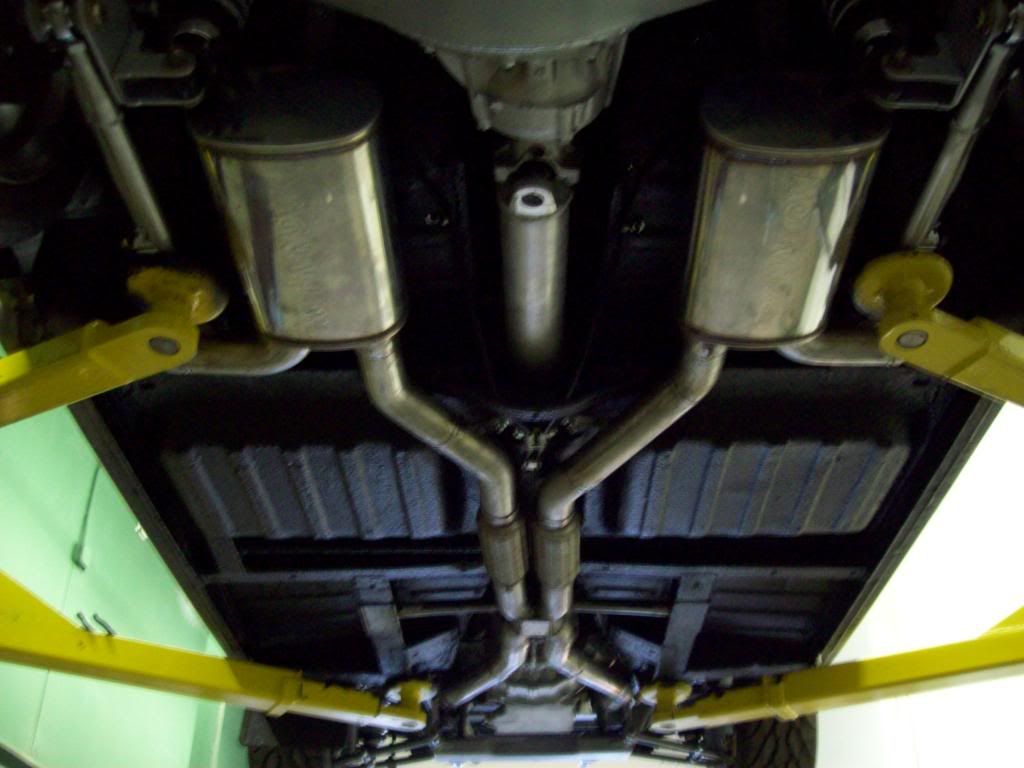
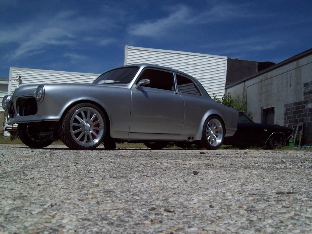
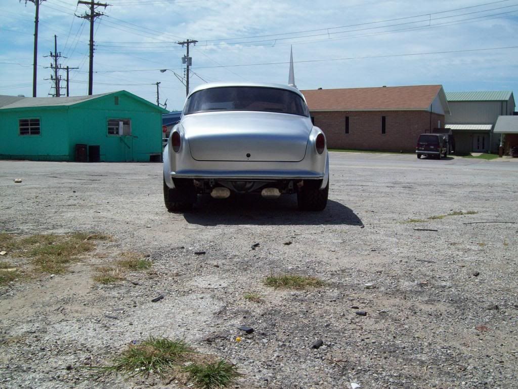
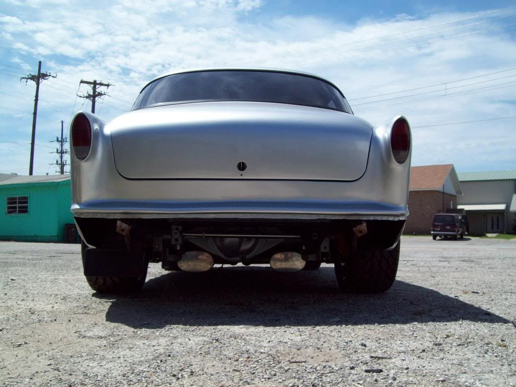
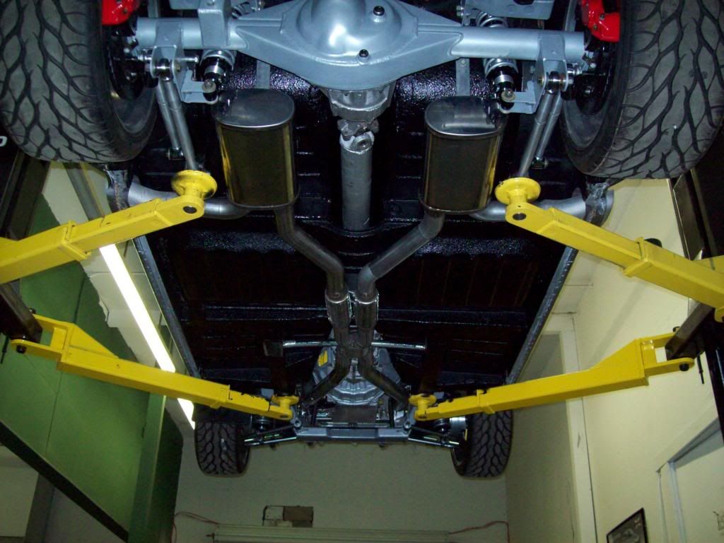
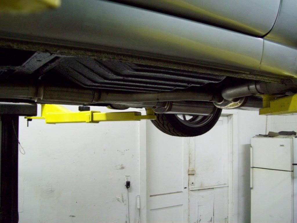
It seems these cars body were made to accept bigger and more powerful items, because the larger dual exhaust fits under the car nicely, due to being able to tuck into the contours of the floor pan and body structure.. Here are some pictures of the car outside, and the pictures were taken low and flat, so you can see the amount of exhaust clearance.. I debated on running a 3in exhaust at one time, and it appears it might have worked out just fine. The wiring you can see hanging down, is the transmission speed sensor wiring, because I didnt have the car on the lift to hook it up during the wiring harness install.

Leave a comment:
-
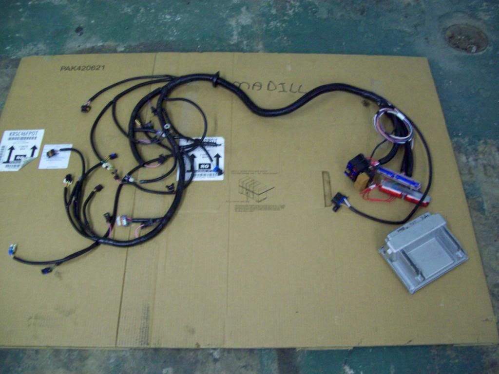
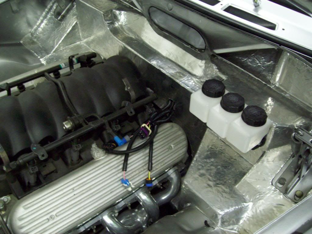
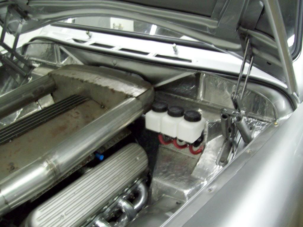
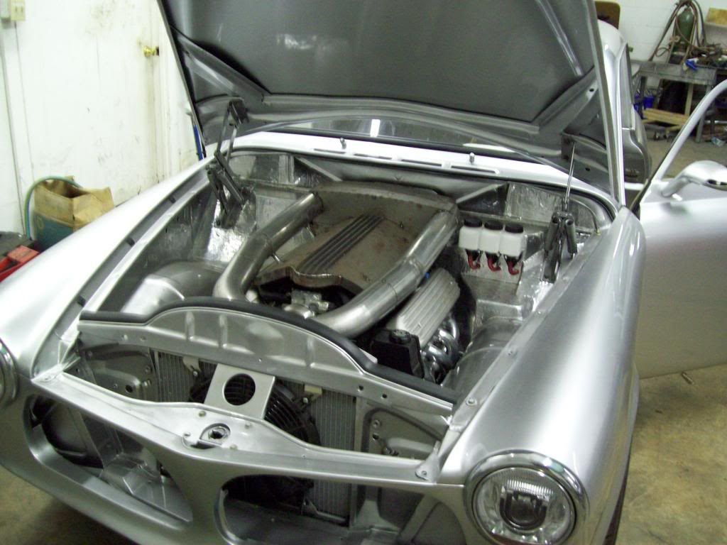
Now we are getting to some really productive updates, and that is because, it will be time to fire this car up very soon.. LOL I dont know why some people are afraid of the wiring and engine management of the LS Upgrades, and you should be able to see by the simple harnes below, that there isnt really anything to them. Once you have your basic Ignition Hot, Ignition Signal, and Ground, you are basically done, and dont have to worry about Timing, Tuning, or any other typical Carburation/Distributor issues. So here are some of the engine wiring and Brake and Clutch master cylinder resevoir mounting, and I think it all came out pretty clean, because it looks pretty minimal.. As far as the LS Engine wiring goes, it is actually very easy and clean, especially if your have your engine management harness pop through the firewall directly behind the motor.. With the way these LS motors wire up, it is very easy to tuck and hide the wiring, so it isnt very noticable at all.
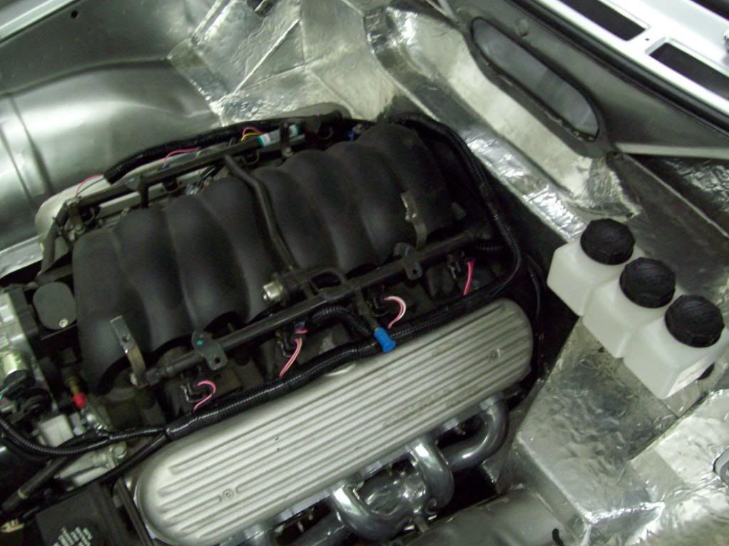
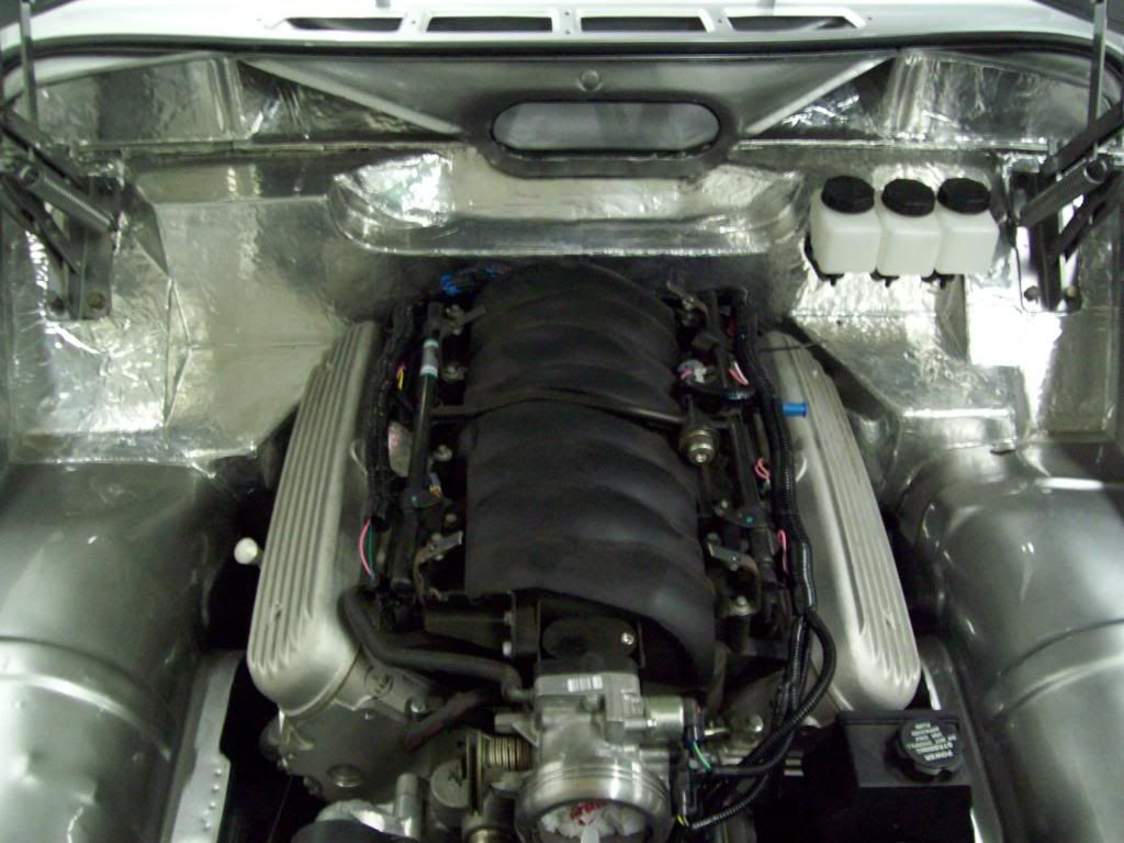
Here is the motor fully wired with the Intake back on it, and as you can see, the wiring is basically hidden. You can do this same thing with the original LS plastic engine covers, or any other basic aftermarket intake cover, and this is one of the reasons I really like these motors
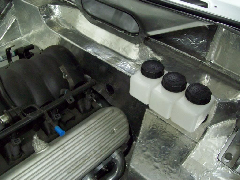
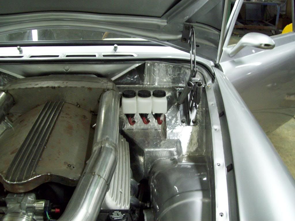
Here are the pics of the final Brake/Clutch Resevoir mounting and plumbing, and it came out pretty simple looking, so it wont be so bad.. I could have mounted these resevoirs directly on the Wilwood Pedal Assembly/Master Cylinders under the dash, and it would have made the underhood look much cleaner, but I dont like the idea of checking and filling brake fluid from under the dash
Leave a comment:
-
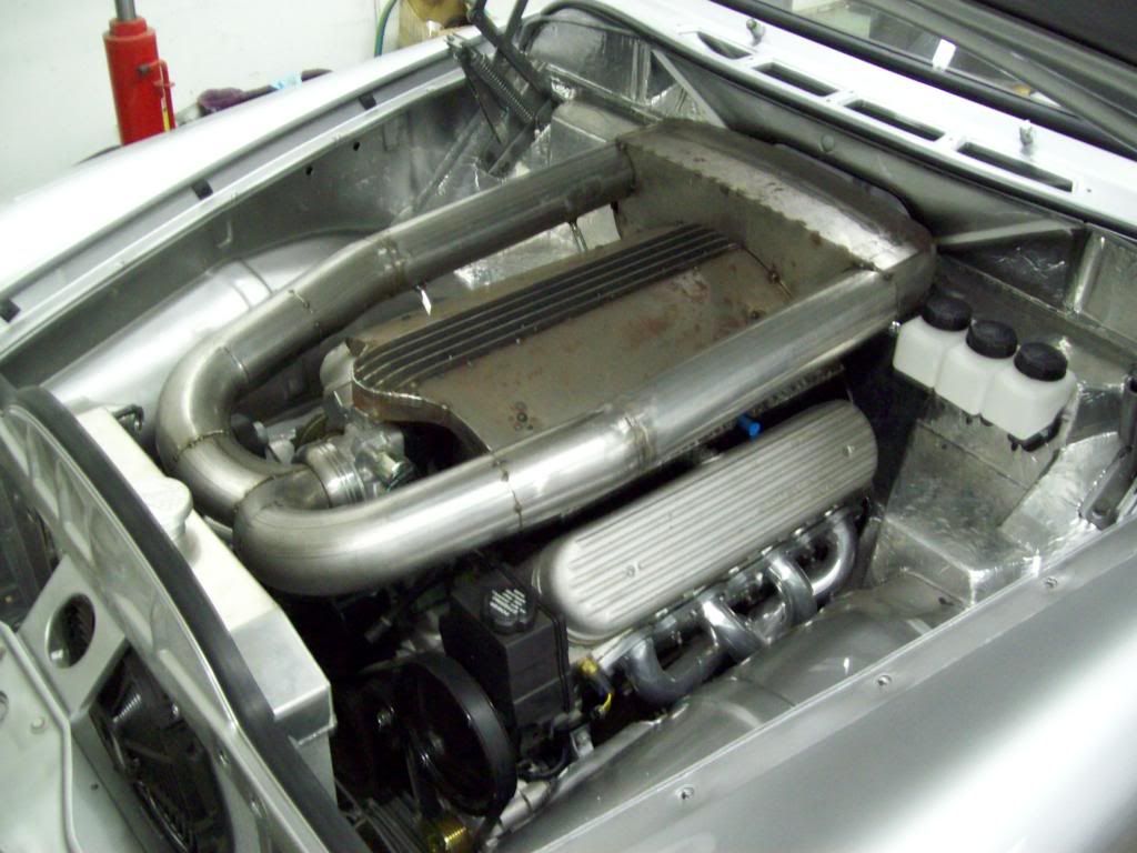
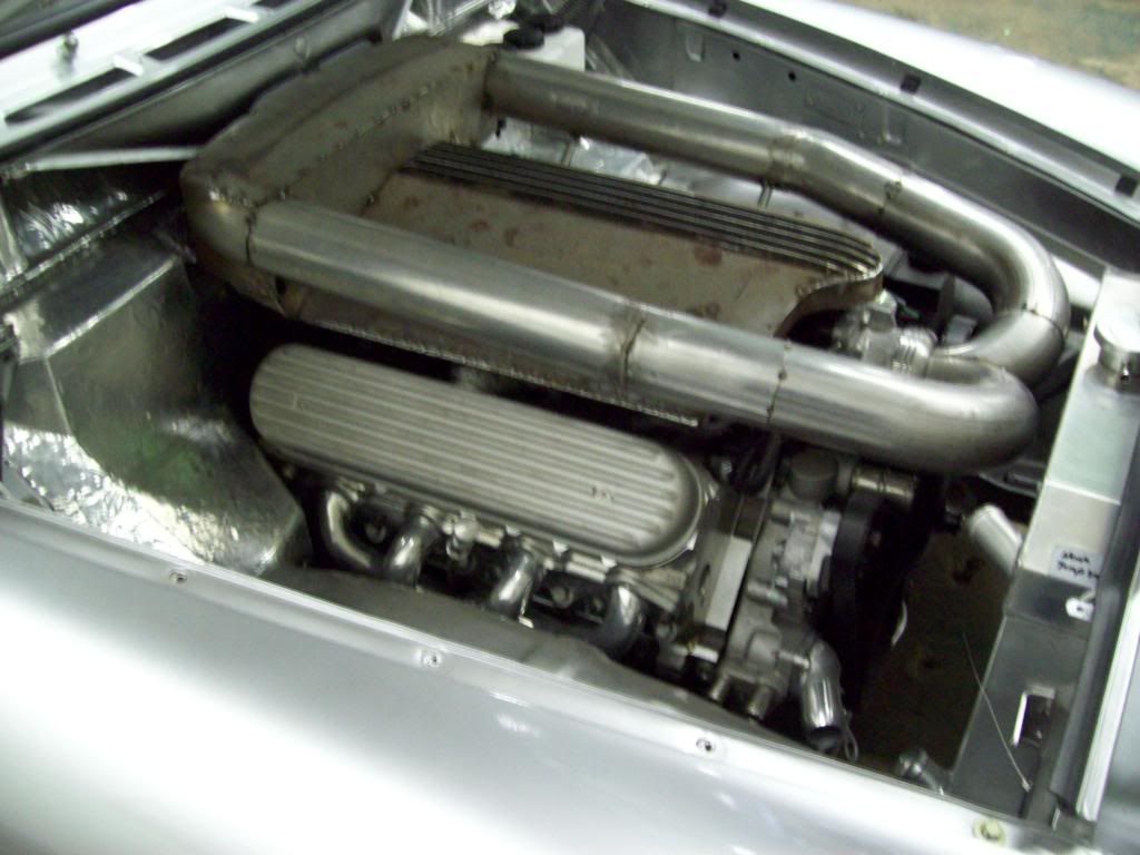
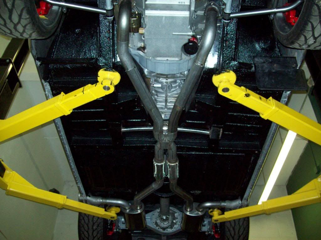
Here are some pics of the exhaust system layout, but I will have to remove it for all the finish welding and protective coating, and also add some sectional flange/gaskets so I can take it apart in sections if ever necessary. I really wanted to run the electric exhaust dumps, but I didnt want to run them if I couldnt have the open exhaust run out the same side tips, rather than dump on the ground. There really isnt a good way to do it, and that is due to space, and the fact I am trying to keep all the exhaust as tight to the body as possible.
I was able to fab the exhaust out of a 2.5in exhaust tubing and mandrel bent ends at the shop, so now I dont have to worry about sending it out somewhere else to get done, because it is rare that the shops around here make any of the bend even. I also tried to take some pictures that would show how it all fits in the recesses of the body, and I would almost bet that it isnt as low as some of the 4cylinder exhaust versions out there.
Leave a comment:
-
Wow... That is beautiful for sure, but I would never consider doing that for a daily driver car that the family rides in.. LOLOriginally posted by Miroteknik View PostLeave a comment:
-
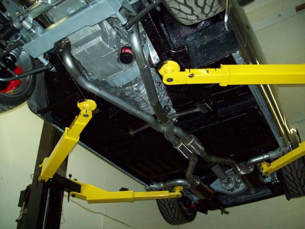
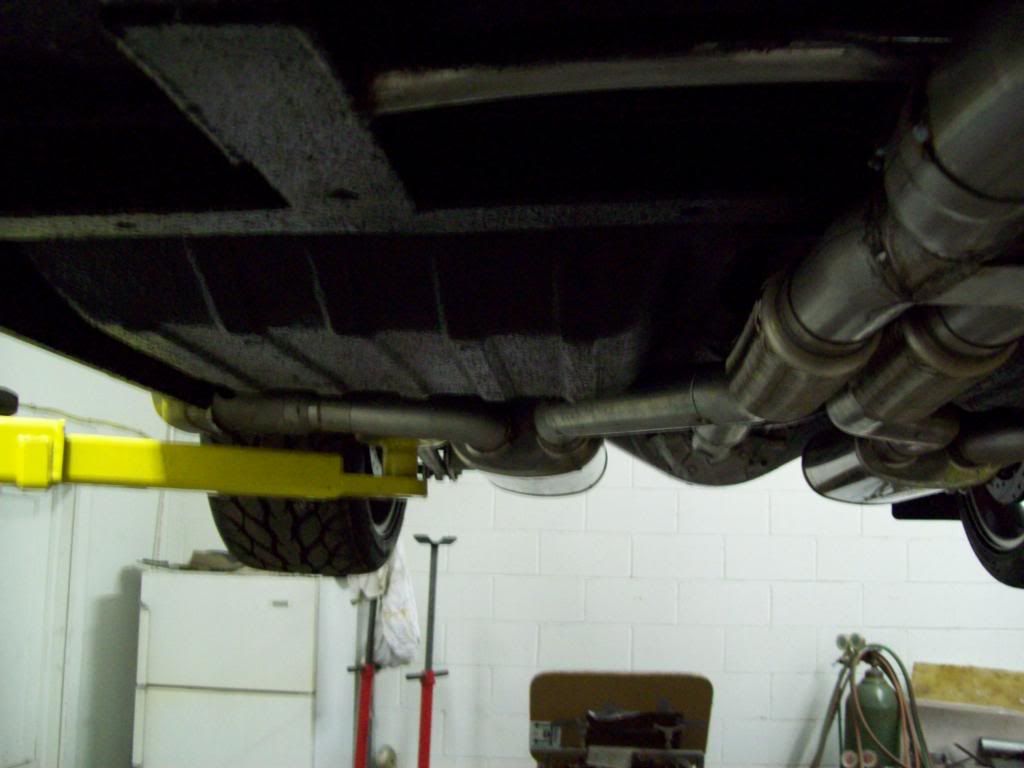
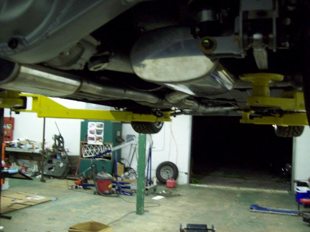
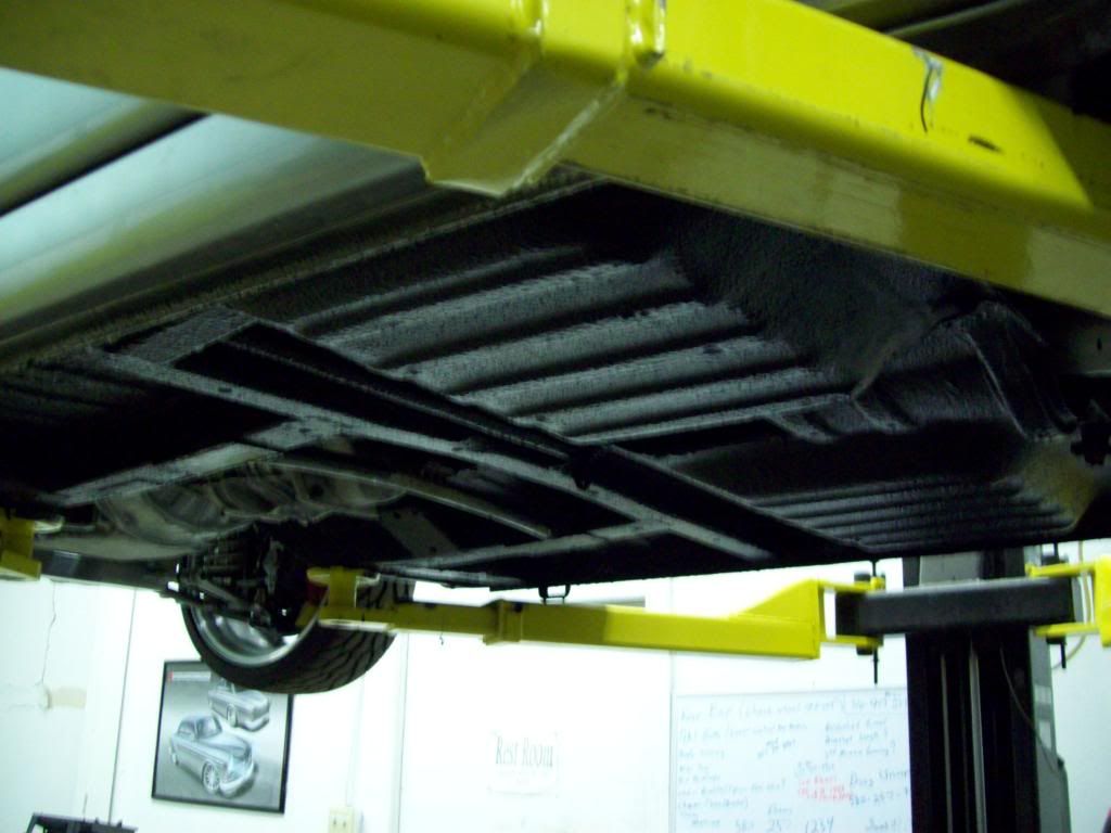
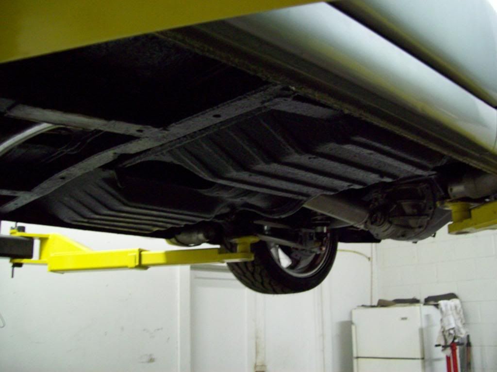
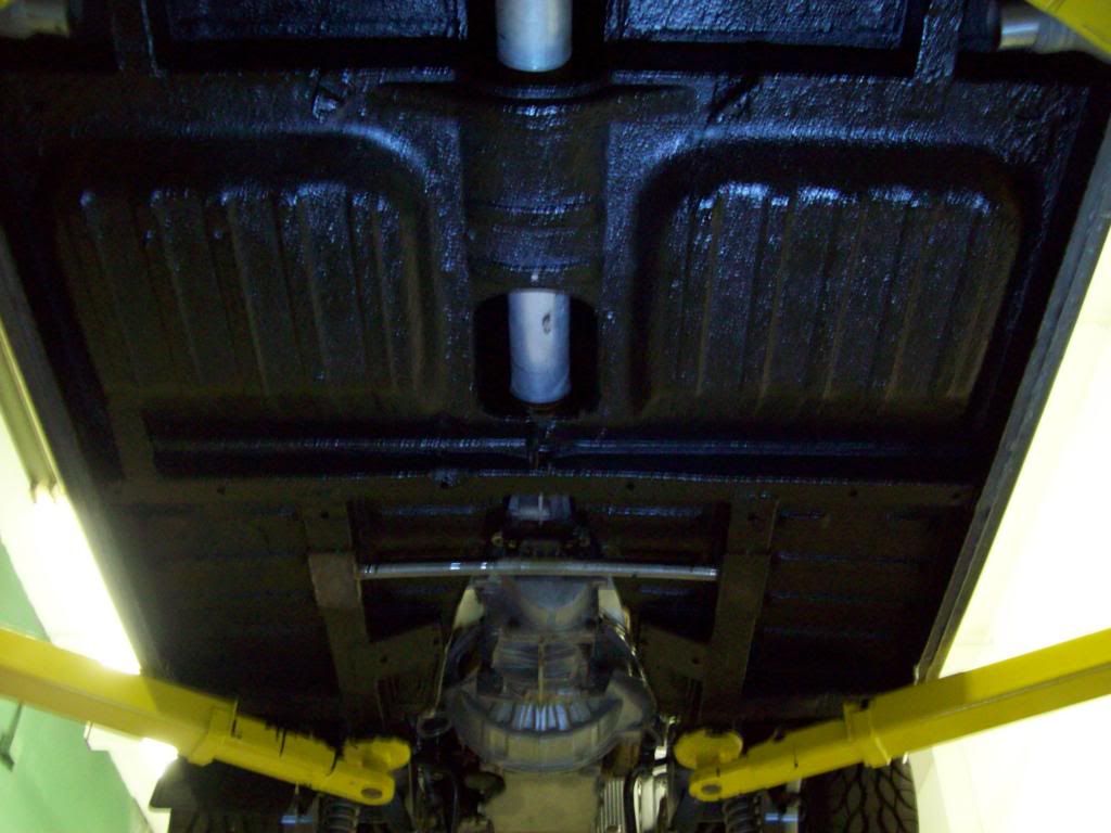
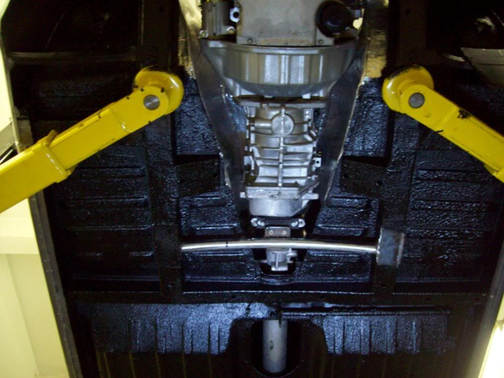
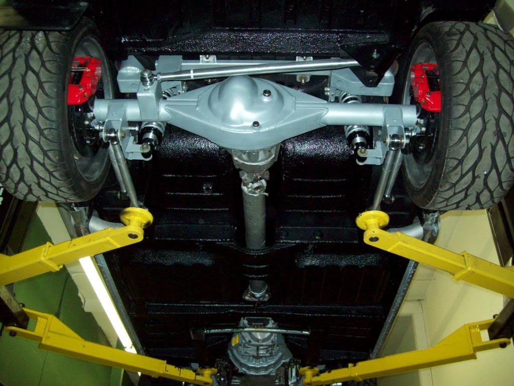
Here are some pics of the bottom side of the car, after I laid down the Bed Liner Coat for extra protection, and it is much easier to keep clean. It looks a bit rougher textured in the pics due to the flash, but it is a very hard and smooth, so dust will not really stick to it at all.. The new driveshaft tunnel works out great, and there is plenty of room to remove it with no effort, along with service the 5-speed transmission.
I still have to put a bit more coating on the area's that the lift blocked access to, and once that is done, it should look pretty uniform.. There will be a bit of extra care taken with this process to the Customer Build Cars, because they will be done in the correct task order, which would have had all of this done prior to assembly. Some of this build process is completely out of order, and does complicate a few things, but it was the only way to work the logistics of everything that is going on with outside sources and services.
Leave a comment:
-
Oh.. I know.. LOL As I said in one of my last post, there were procedures that needed be done out of order, due to the scheduling necessity of body/paint work and the rest of the components.. Now it is really a matter of completing items like the trans tunnel, without damaging the previously done paint work, and luckily I havent scratched the car yet.. LOL Good news is, I am really about done with all of that at this point, so now it is the typical plumbing and wiring task coming up..Originally posted by evilstar View PostLast edited by Iamtheonlyreal1; 06-23-2013, 01:27 PM.Leave a comment:


Leave a comment: