-
Nice job on the retrofits. What projector did you use? I never seen the Gatlin Gun V2 actually mounted before, so it looks really clean. -
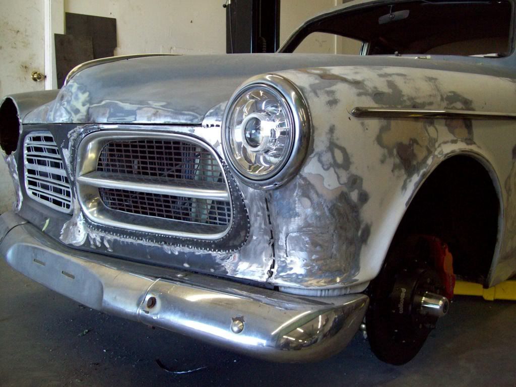
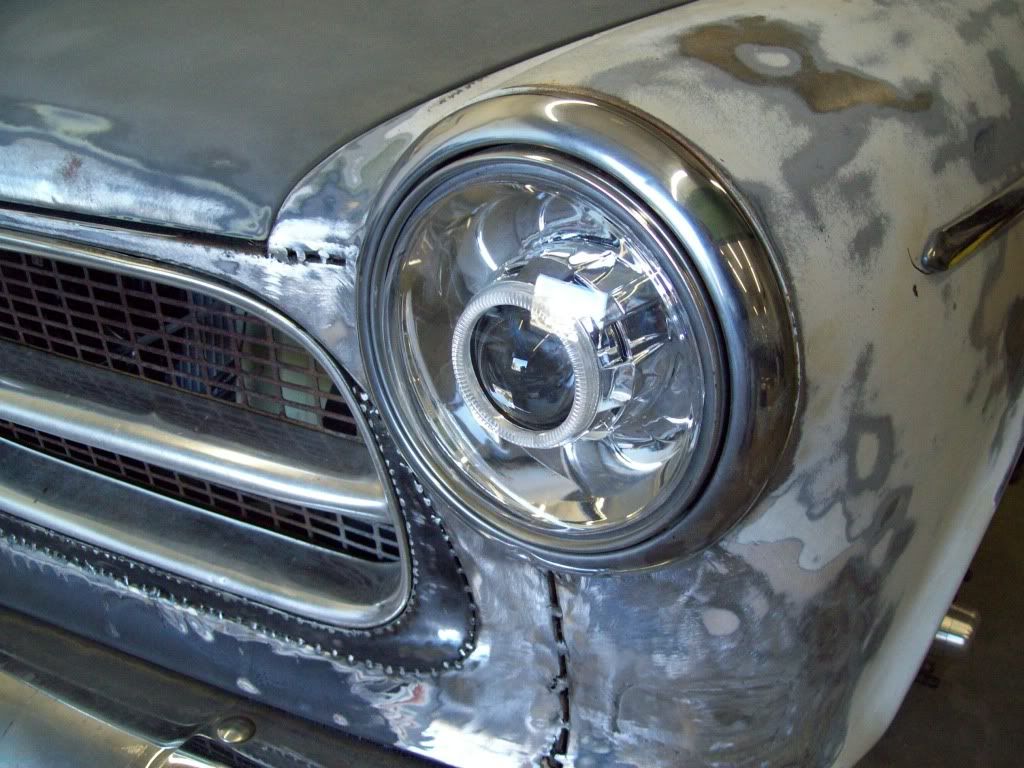
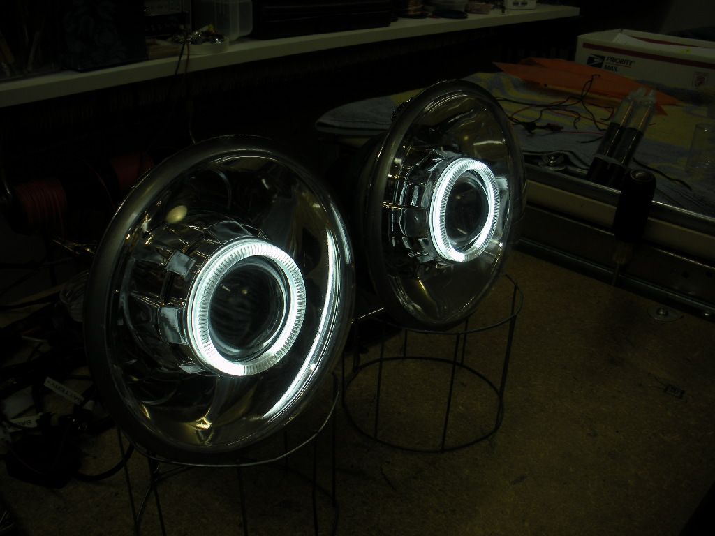
Sorting out the lighting at this time, and will be trying to clean it up a bit.. I have some custom made HID Projector Headlamps that I had made, with the LED Halo daytime running light. They are smooth lenses, and smooth reflectors, which really make the headlamps very crystal and clean.
In the renditions the headlight ring in painted body color, and I think I am going to try it both ways, before I made a decsion on which one stays.. I am removing the chrome tail light housing, so it I leave the headlamp ring chrome that might look out of place. The renditions for the Amazon builds, have the headlight rings and tail light bezels painted body color, and I think that looks best.
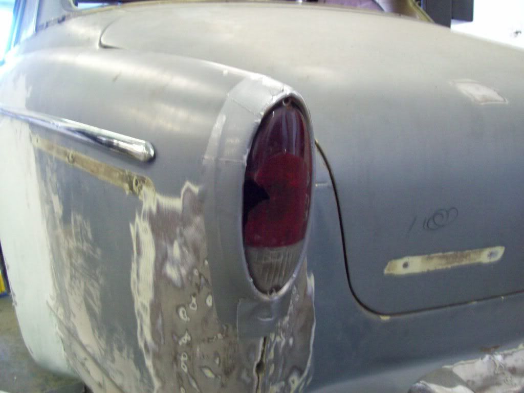
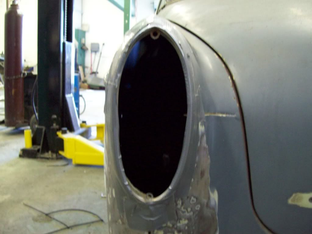
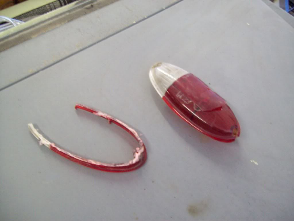
For the rear tail lights, I wanted to clean up them up a bit, really only by getting rid of the gasket system. I found that if you do just a bit of trimming to the tail light lense, you can install it from inside the body, so I will be welding the bezel to the end of the quarter panel.. This will eliminate the need for the rubber gasket, and will allow me to paint and blend the bezel into the body, to give the quarter panel a completed look..
Leave a comment:
-
Not trying to pull over anything on anybody, but I did forget to point something out about this procedure, and I was reminded by another viewer that I need to disclose this information..
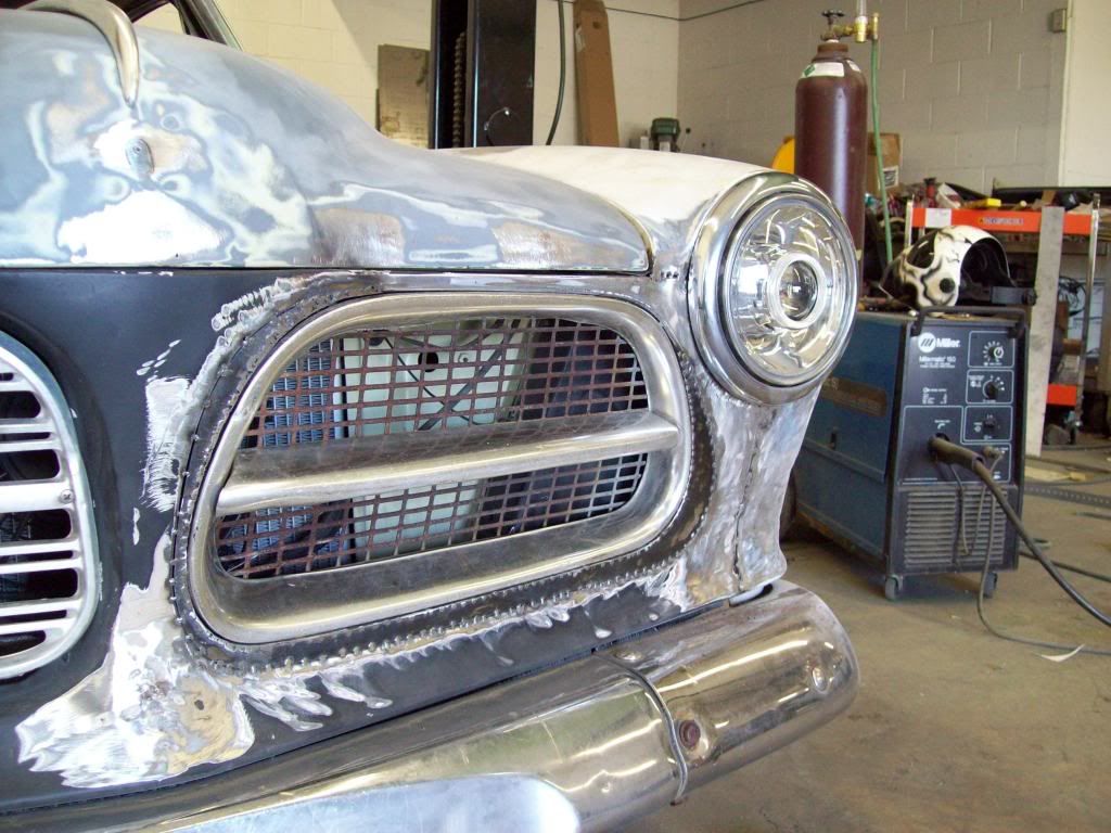
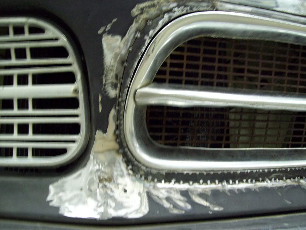
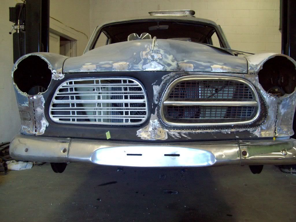
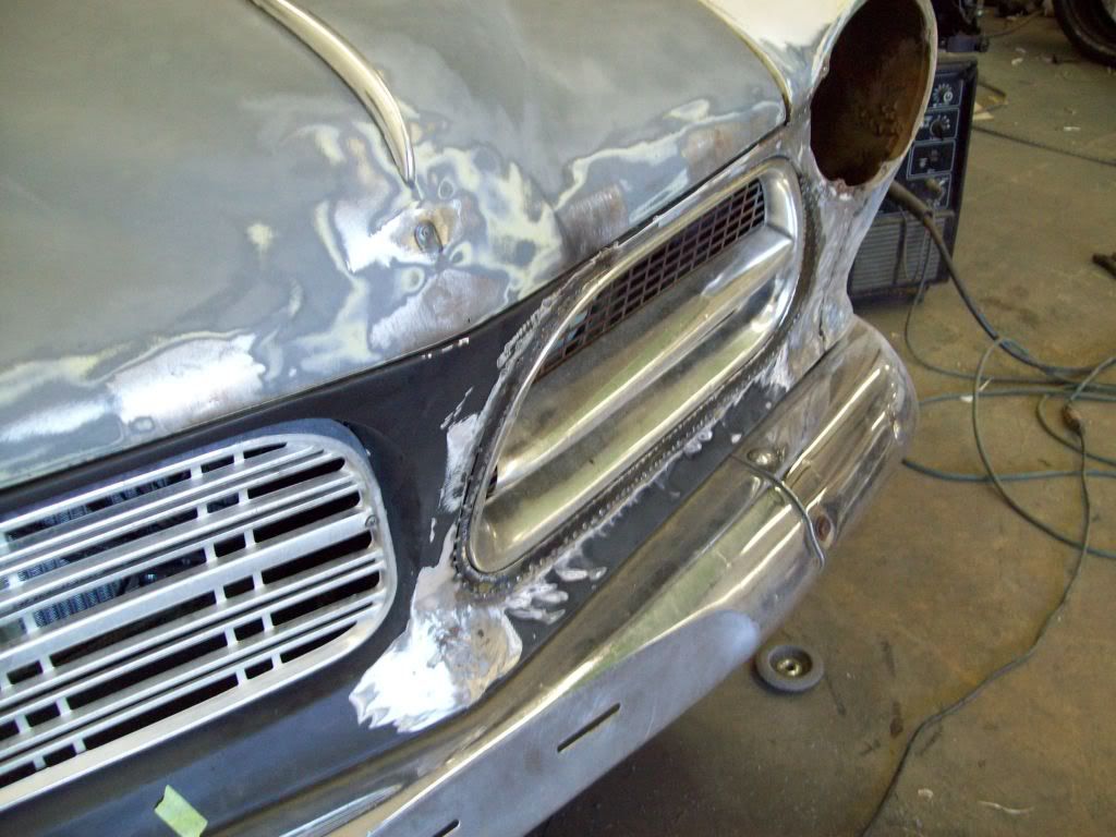
The grilles are actually on the opposite side, which isnt really that noticable, unless you have a trained eye. (Derek) LOL The early grilles fit better in the later facia, if they are on the opposite side, because you dont have to actually cut into the later facia panel. The early grilles dont level out correctly in the later facia, unless you drop them down too far, or you do some structural cutting to the later facia.
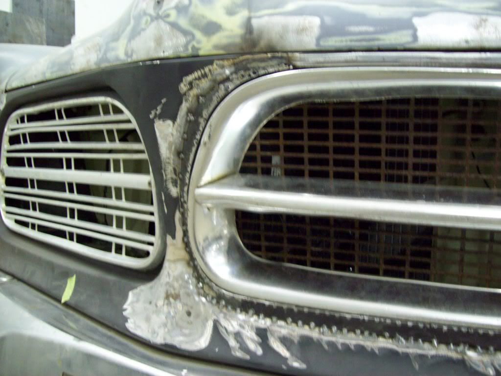
I had intented on mounting them in the OEM position, but in laying them out in their opposite positions, I noticed that the deeper ring side of the grille, actually complimented the center point/bulge of the hood and grille facia, because it added an additional appearance of depth to the center extension of the facia.. It may not be that noticable in the pictures, but it does make a difference in person.
Here are a couple of pictures to show what I am talking about when it comes to one side have more ring depth, and how it accents the center of the nose, rather than the fender.
Original Side

Opposite side, with the deeper grille ring accenting the center of the facia.
Leave a comment:
-
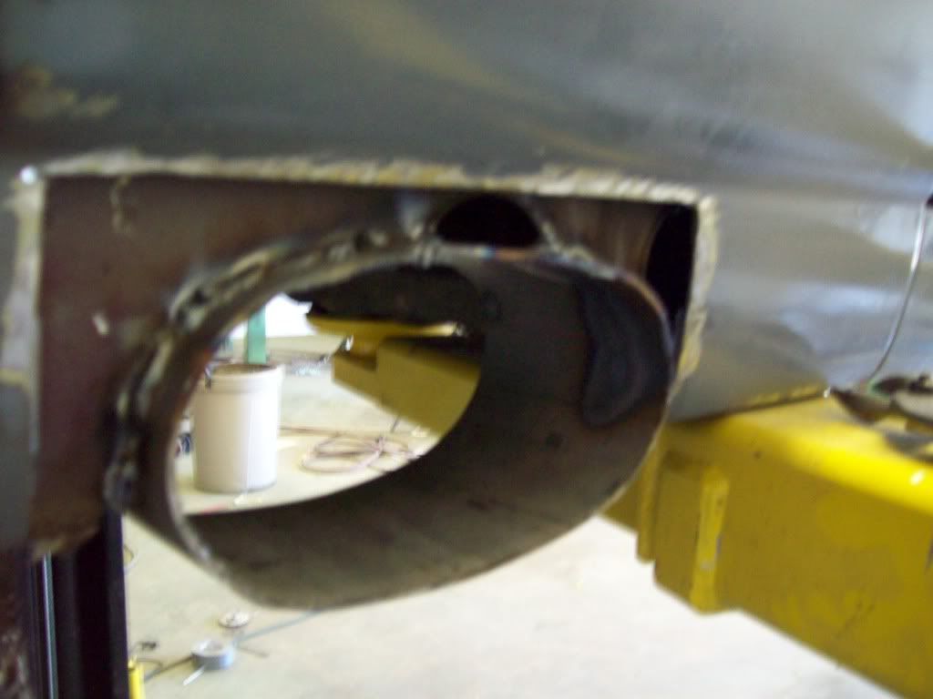
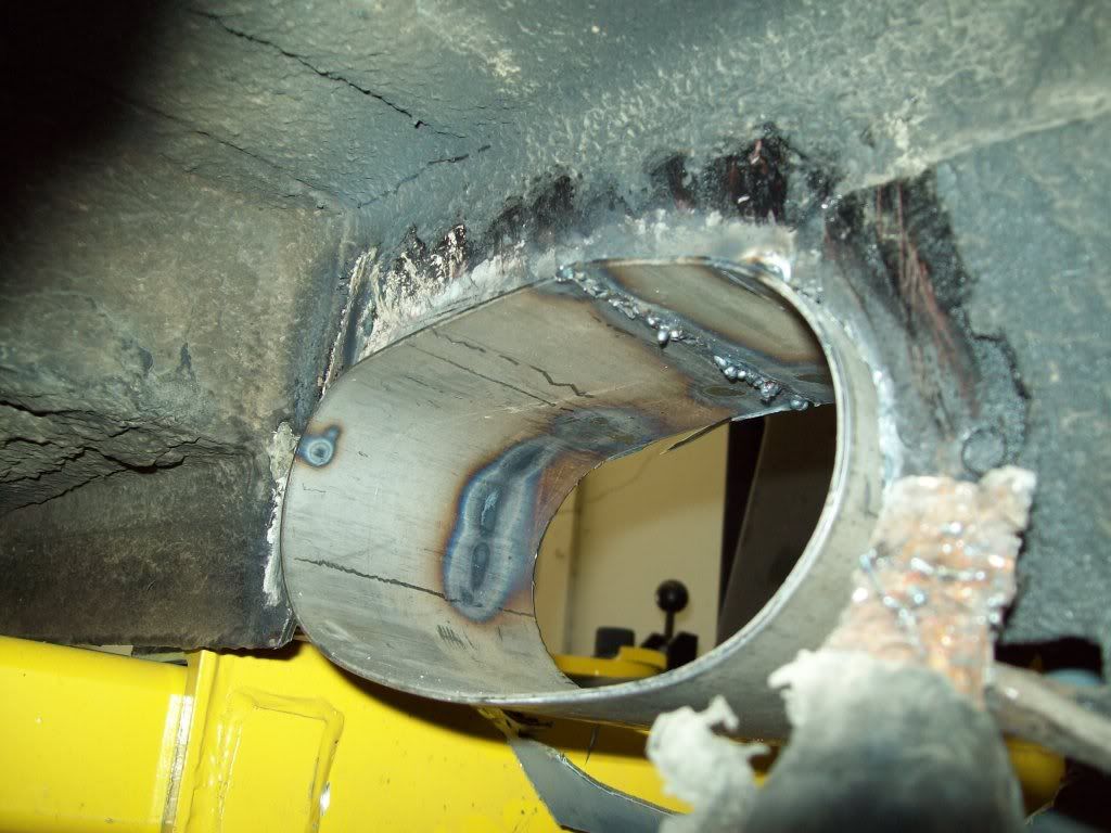
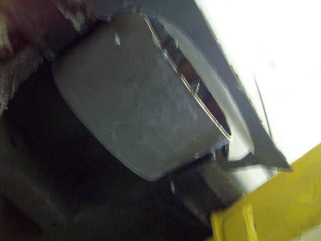
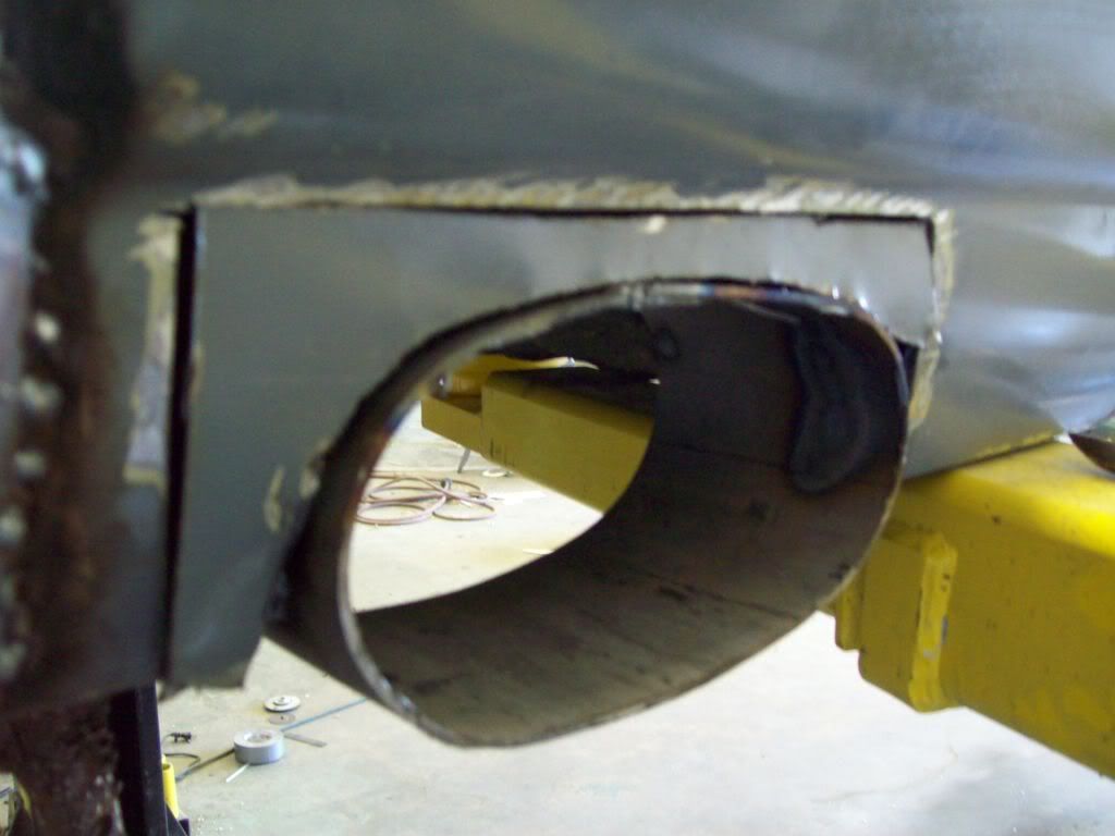
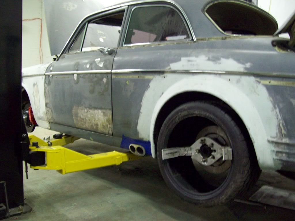
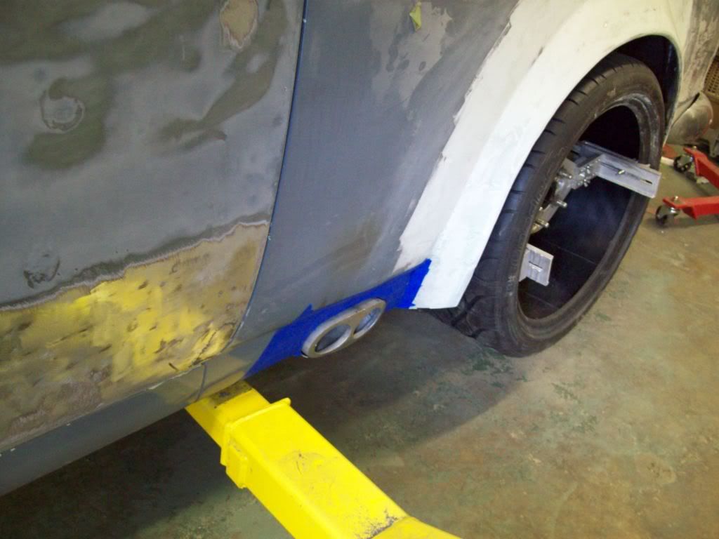
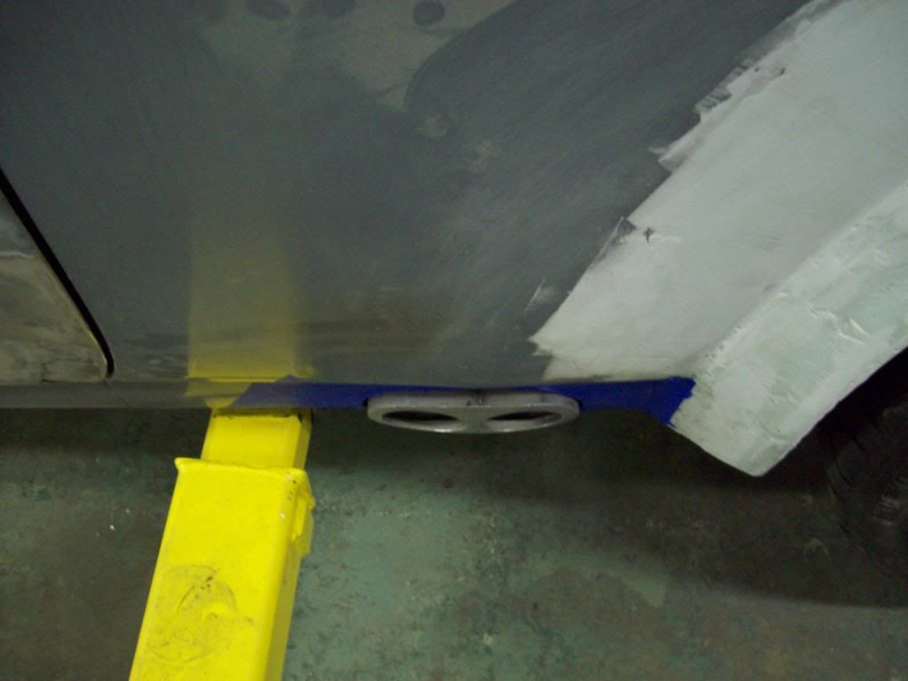
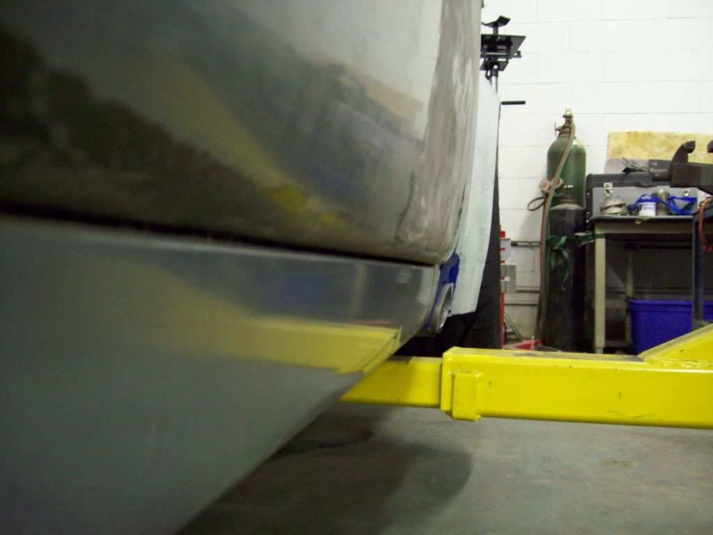
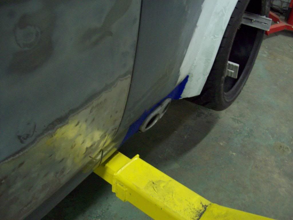
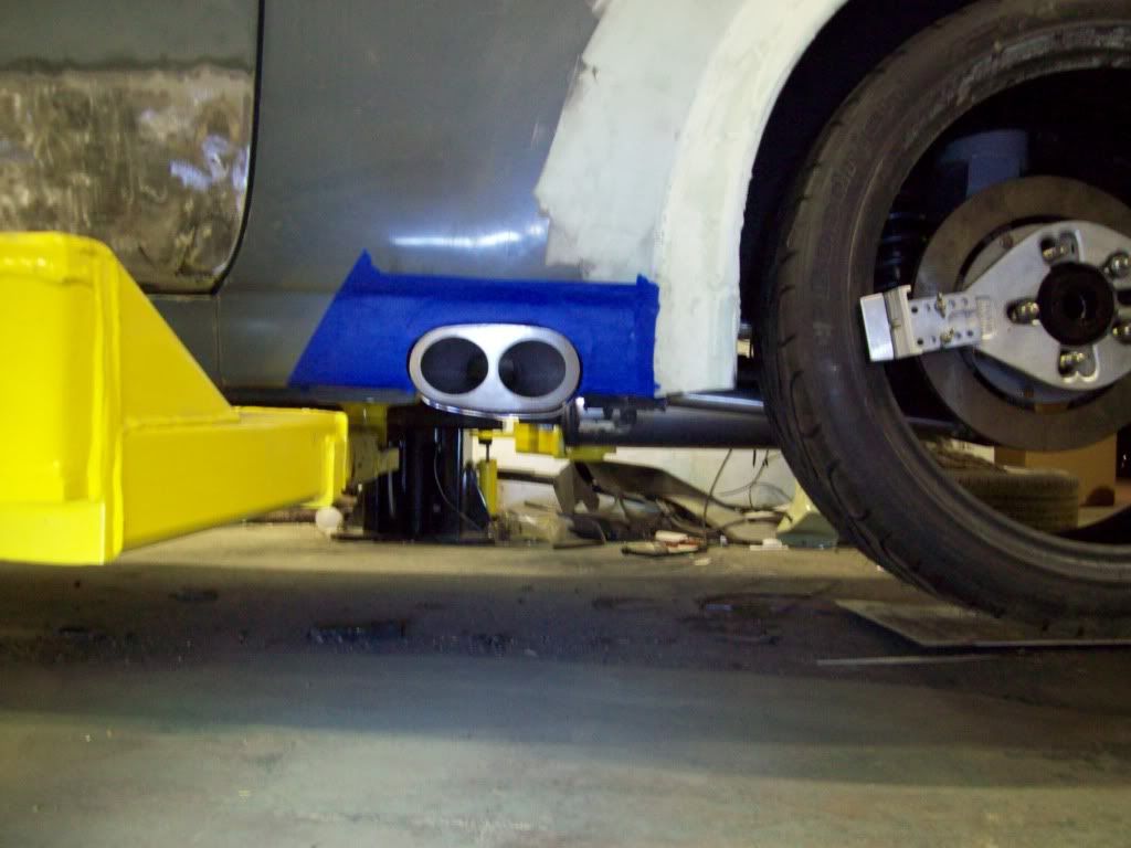
For the guys that have asked for the side exit exhuast, here are a few pictures of what I had done.. I apologize for them being grainy, but I didnt realize it, until I had things buttoned up..
It is very important to make sure that you open the rocker panel skin up to a larger hole, so you have access to weld the new exhuast loop to the inner rocker structure, otherwise you will only be welding to the weaker outside rocker skin..
Leave a comment:
-
I couldnt take leaving the later grilles in this build, and I didnt have the best of luck sourcing a new facia, so this is what I came up for a solution.. I had some old style grilles that I bought off Ebay about a year ago, and it was bugging me that I couldnt use them, because they look so much better than the later grilles. Here is what I came up with, so I will show the relatively inexpensive and simple alternative, and hope this helps someone else in the same situation..
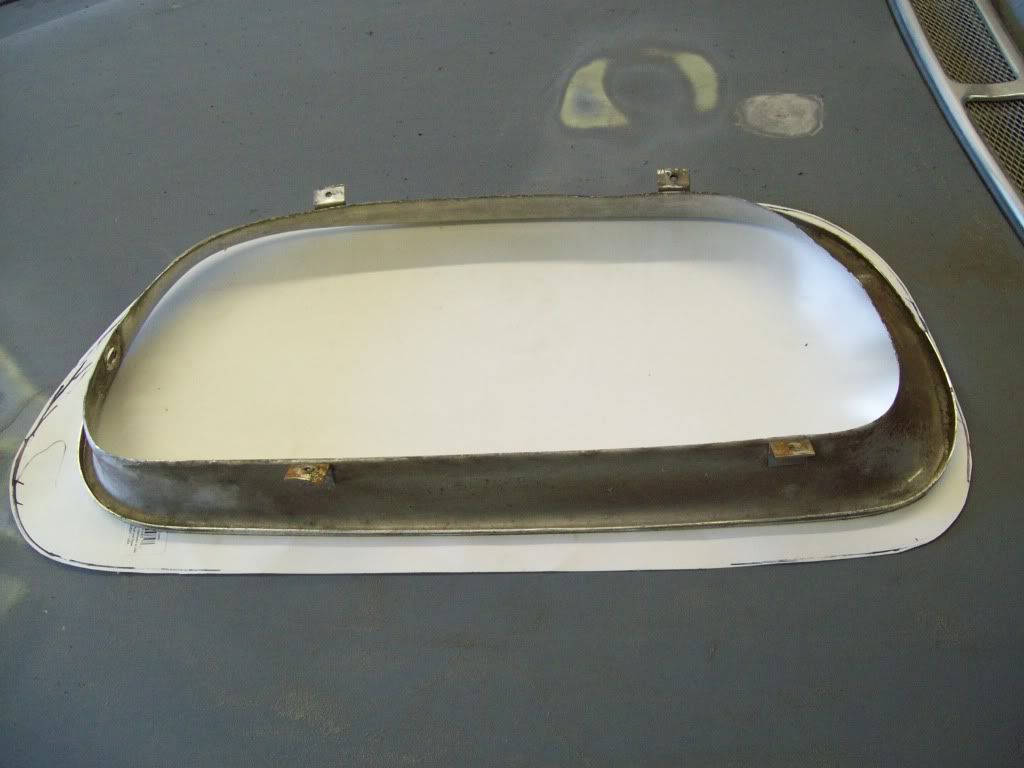
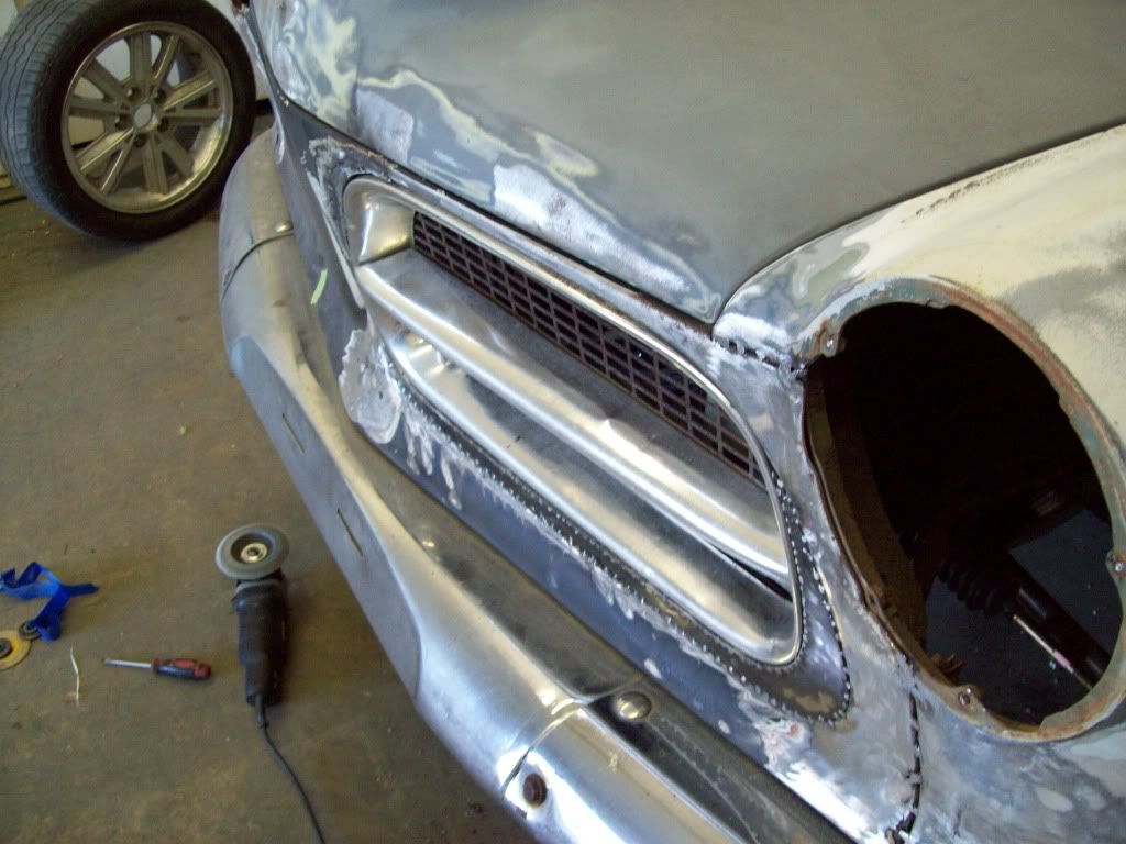
The first thing I did, was to make a poster board template of the later grille shell hole.. I had a donor grille shell, but it could be done on the car, so you dont have to take the facia off the car.
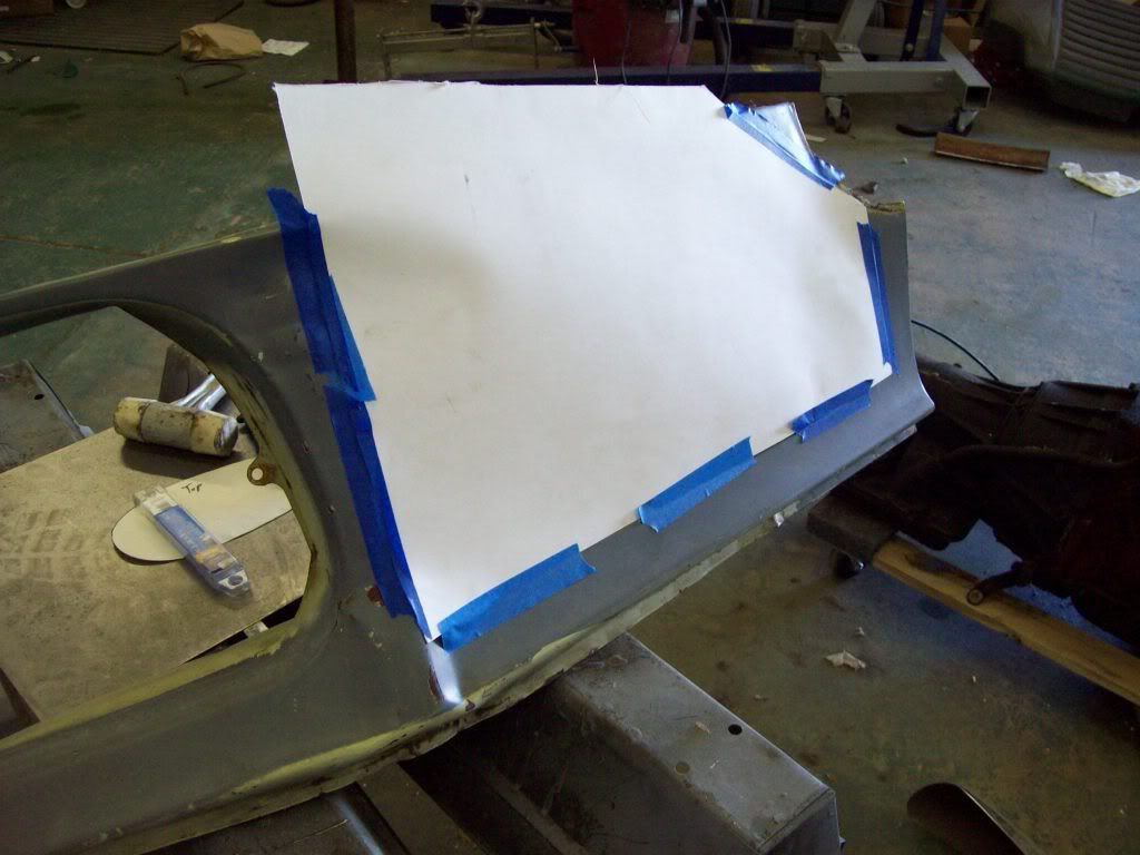
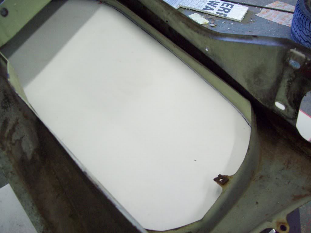
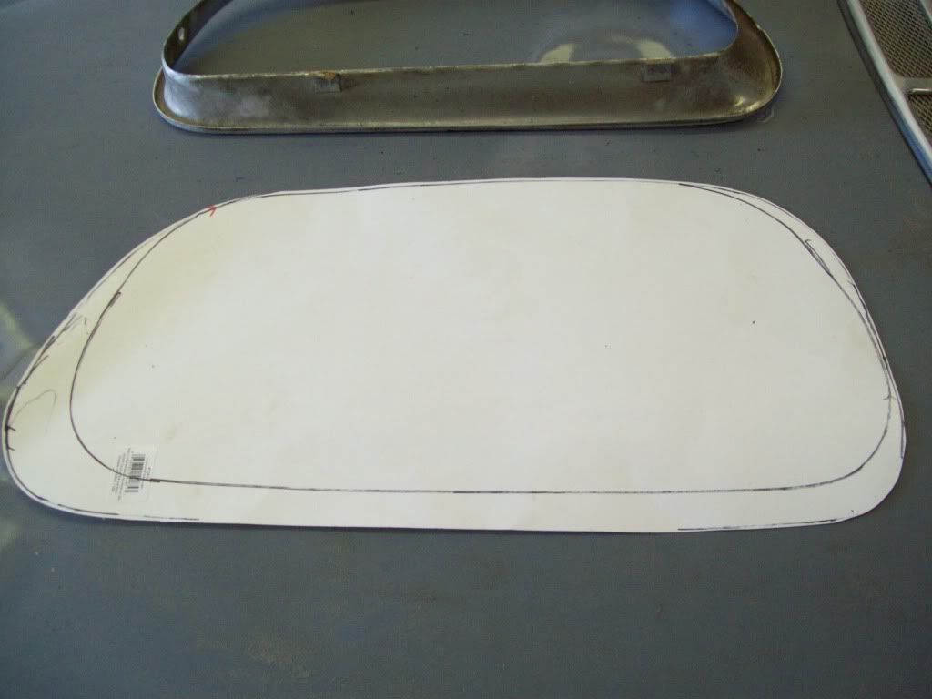
After you use a marker to outline the hole, you will cut out the template of the later grille shell hole, which you will then be able to use the early grille to mark the new hole position, which will leave the actual piece of metal that you need to weld in the later facia.
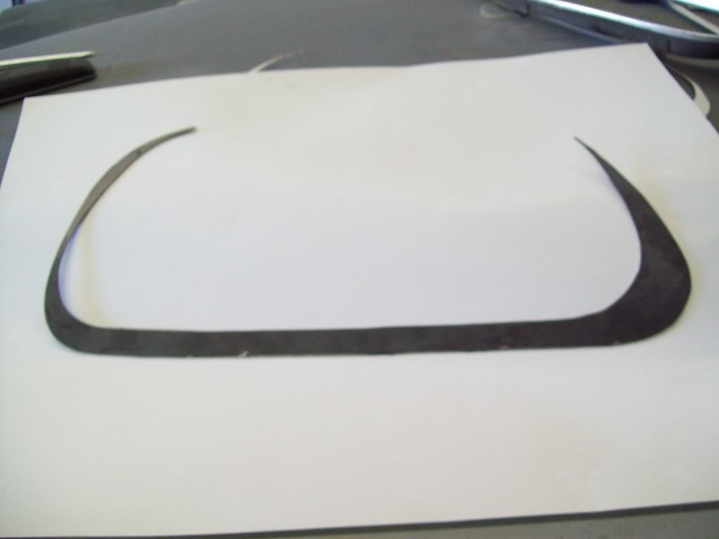
If you flip the grill upside down on the template, you can then find the grilles reference position on the the later hole template.. This is relatively simple, because most of the upper and bottom of the early and late hole is the same.
I used a 4.5in angle grinder with a cut off wheel to cut out the piece from the sheet steel.
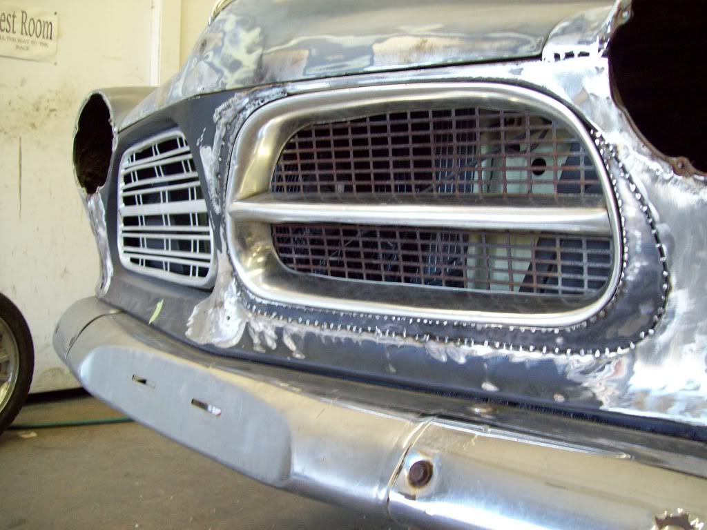
After that, you can put the new filler piece in place, and then you will have a bit of grinding to fine tune the fit. Once that is done, you can tack weld it all in place, and then do some finish grinding to make sure your new grille opening is the right size and contour.
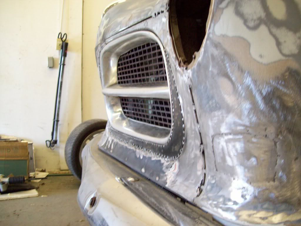
Once you are satisfied with that, you can then add the inside boxing sheet metal, by rolling it and tacking as your continue around the new opening.
After all that is tacked in, keep checking your new grill opening, so you can make sure nothing has change during the postioning and tacking procedure. After you are insure the fit is where you want it, you can then do the finish welding, which is where I need to continue from the pics seen.
It appears with just a bit of hammering and grinding, along with just a bit of filler, the early grilles will fit nicely. I still have to make the mount tabs at a later date, but I will wait until I get the new opening finished out nicely, because that could change something if I made the tabs now.
My grilles are not the straightest at this moment, so I will need to locate some better ones to work with for the final fitment.
Leave a comment:
-
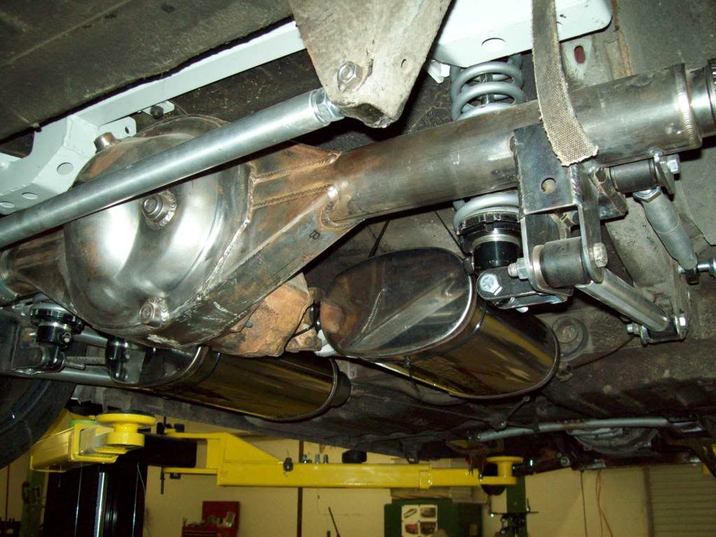
I am thinking that I should get plenty of exhaust vibration insulation by running the pictured flex joints below.. The mufflers, tail pipes, and tips will be rigidly mounted to the body, but will still be mounted on a very dense rubber bushing, so they should be very solid..
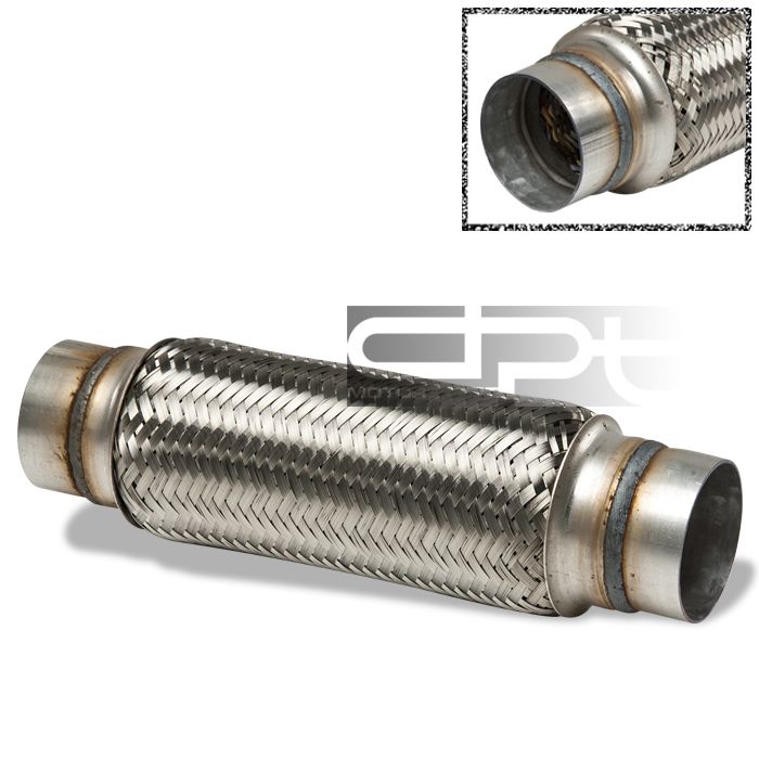
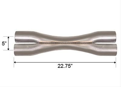
The exhaust pipe coming off the headers will go into the x-pipe pictured below, which will let me keep the header pipes running tightly down the center of the car, between the floor pans for a tight ground clearance fit. The Flex joints will be mounted between the x-pipe and mufflers, and this should allow me to get an extreme body hugging exhaust, and not have to worry about tolerances and rattling..
Leave a comment:
-
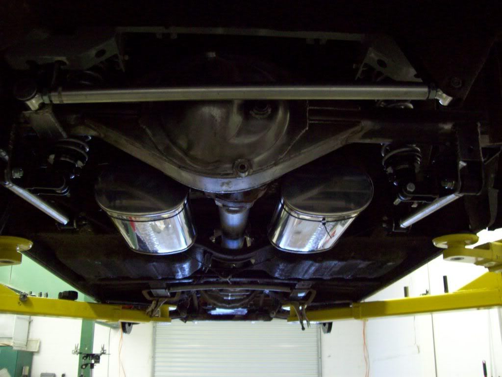
The exhaust tips were just a bit tricky, and I know I going to have a bit of specialize pipe bending to get them hooke up, but it is doable.. I am planning on solid mounting the actual mufflers and exhaust tips, and have a small flex joint betweeh the exhaust header pipe to the muffler. I dont want to take any chances of exhaust tip rattle in the body, and I would like the air gap to be a constant.
Here are some pics of the basic layout, and I think they work out great, eventhough I would have actually liked them just a bit further back, but that wasnt optimal for exhaust pipe plumbing. The perspective will change a bit, once the car is on the ground, and it is out in the open.
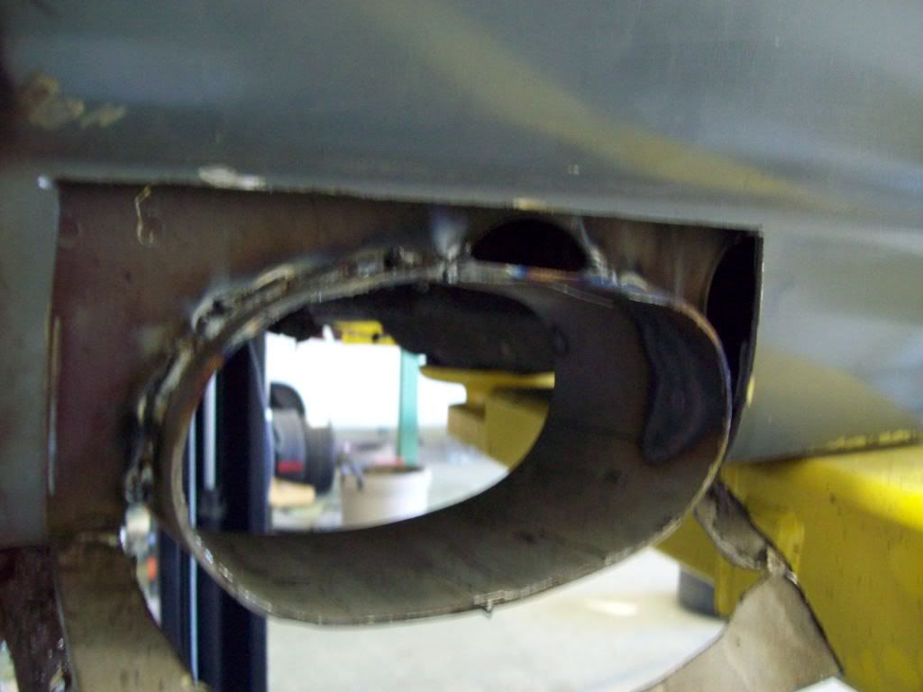
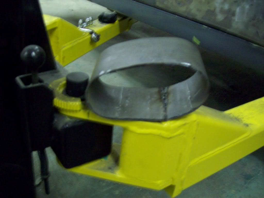
This is the box piece that I made to close off the cut hole.. There is access for proper finish welding to the body/rocker support, so I dont have any worry about any weaking of the body structure, and I dont see how it couldnt have actually strengthened it..
Leave a comment:
-
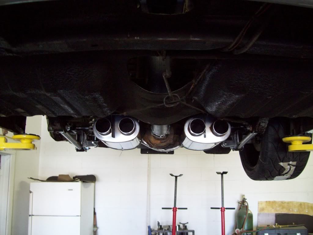
I am waiting on my exhaust tips, so I can build the rocker cut out/box, but I did mock up the Magna Flow mufflers, and it appears this exhaust configuration will work.. I am debating on solid mounting the mufflers and exhaust tips, and using a small flex joint to attach the header pipe to the inlet of the mufflers.. I am wanting to keep a fairly tight tolerance with the exhaust tips running through the body, and I think that might be the best way to solve any rattling issues.?
Here are some pictures of the Magna Flow muffer placement, and if I solid mount them, I will pick them up just a bit higher. The are up there pretty tightly now, but I would like to have them totally above the rocker pinch weld, and they are very close to being there now.. These mufflers are just tacked up in a mock up position, so they are not at the exact hieght and perfectly centered/level, but you should get the idea.
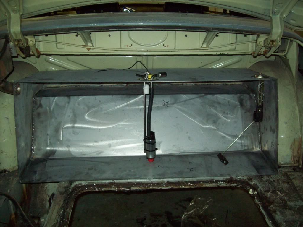
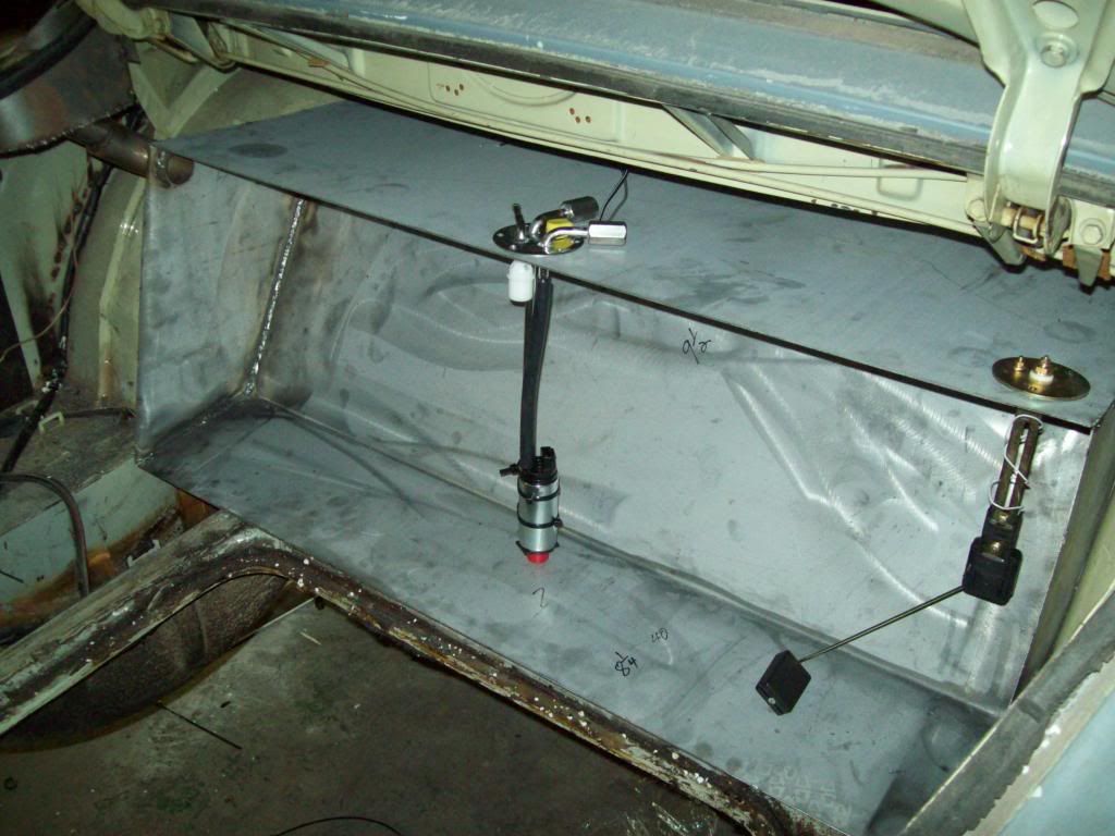
Here are a couple of pics of the Fuel Tank alterations.. As you can see, I brought the tank down in height a bit, because it worked out to be about 26 gallons, which is way too much fuel to carry. The tank is just under 18 gallons at this point, which should be about perfect.
I have positioned the fuel pump/pick up and fuel level sensor, but have not installed the fuel pump pick up baffle yet.. These tank will work with an internally mounted fuel pump, along with a external or manual fuel pump, so it should fit alot of applications.
Leave a comment:
-
Dont you just **** it when someone comes around and makes you look like a dumbass? I have been debating on what to do about the stainless side moulding for a bit, because I do like the look of it. So I have cut, hammered, bent some old use trim I had, in order to figure out some way to use it.. The rear flare work got in the way of the trim, so tried to make it bend over the flare, along with cutting it before and after the flare, but none of looked worth a damn, so I told my body guy to start welding moulding holes..
Anyway, a friend of mine stopped by the shop today, and looked at it for about 20 seconds, and then said " Why dont you just raise its position?" At that moment I felt like a complete dumb ass, because I didnt come up that elementary solution.. The only thing that makes me feel a bit better is, I dont know how many other people looked at this situation, and no one else made that suggestion either.
Anyway, here is the pics with the trim in its new position, and I dont think it will be that noticable over the stock location. Now I need to find a good source for some perfect new side trim, or some exceptional used pieces.


Leave a comment:
-
Got the first mock up tank in, but we left the back all off, so I can position the filler, baffles, and outlets for the productiong fuel tanks.. They will be in stainless, rather than the steel example here, because this one is only being used for mapping out accessories.. On the production fuel tank, the front, bottom, top, and back will all be one bent piece, with just two end caps welded on.
I haveent figured out the fuel capacity of this tank yet, but I am thinking I might have to reduce some of the size.. I was targeting about 14-16 gallons, and I think I will be closer to 20 gallons on this one, which I am not sure I want to carry that much fuel. I am also debating on an internal fuel pump, because I would rather have the smallest gaskete openings possible, being this tank is actually in the trunk.
Pictured below is the tank without the back wall, so you can see the basic shape of the tank, and the actual space it is removing from the trunk... Most of the space being taken up, is the step up between the wheel wells, so there is still plenty of trunk room left. As you can see also, I made the gas filler tray seperate from the fuel tank, which will make service the tank much easier, because it just sets in place.


Leave a comment:
-
I scored some pretty cool old exhaust tips, and will be running them through the rocker panel at the front of the rear wheel. I like the fact they are cast aluminum, because I think they will go with the color and trim them of the build. I have the MagnaFlow mufflers coming, and it appears they will work out great for this type of application, because the inlet and outlet are coming out the same end.
This will make the overall exhaust system way more compact, because I have a nice floor board pocket in front of the rear axle for the mufflers, and then it is a quick bend out to the correct outlet position at the rocker panel.


Leave a comment:
-
my jaw is on the floor... there are just no words to describe how awesome this isLeave a comment:
-
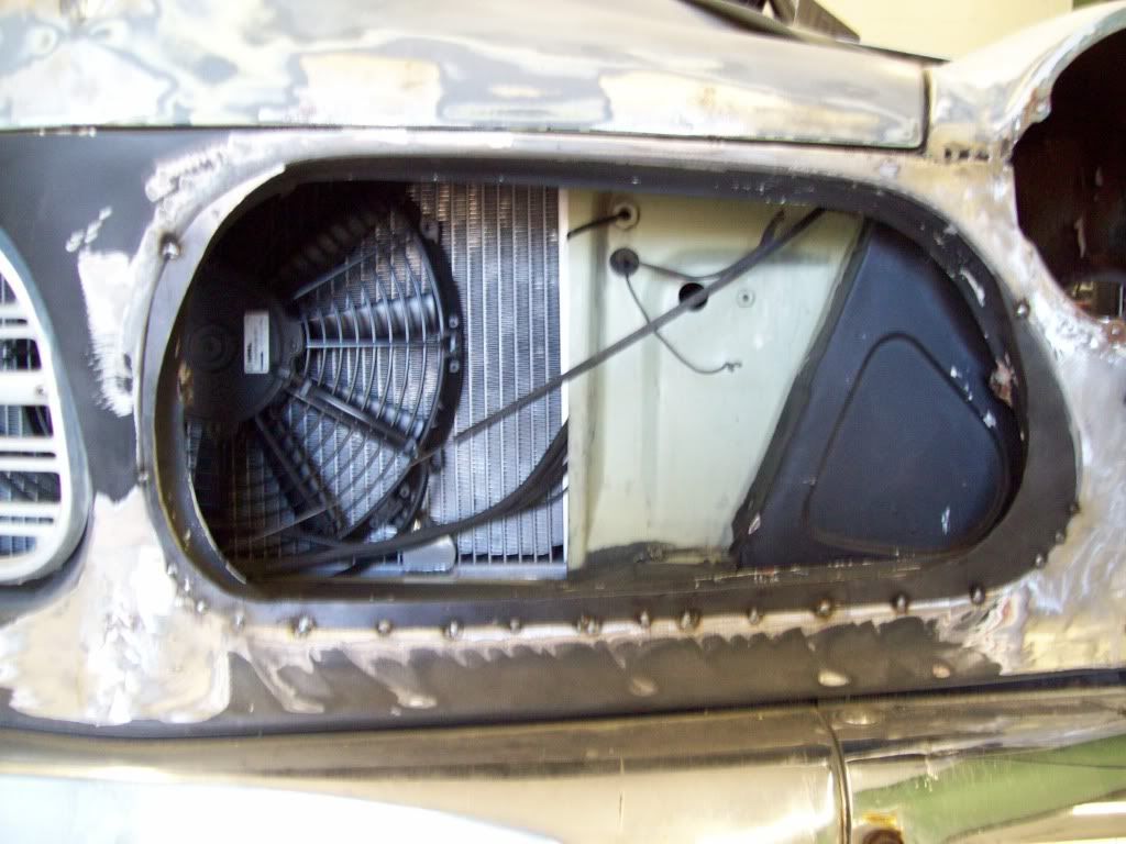
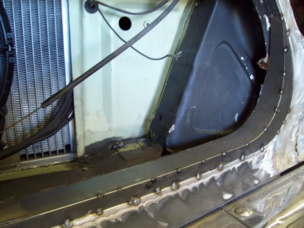
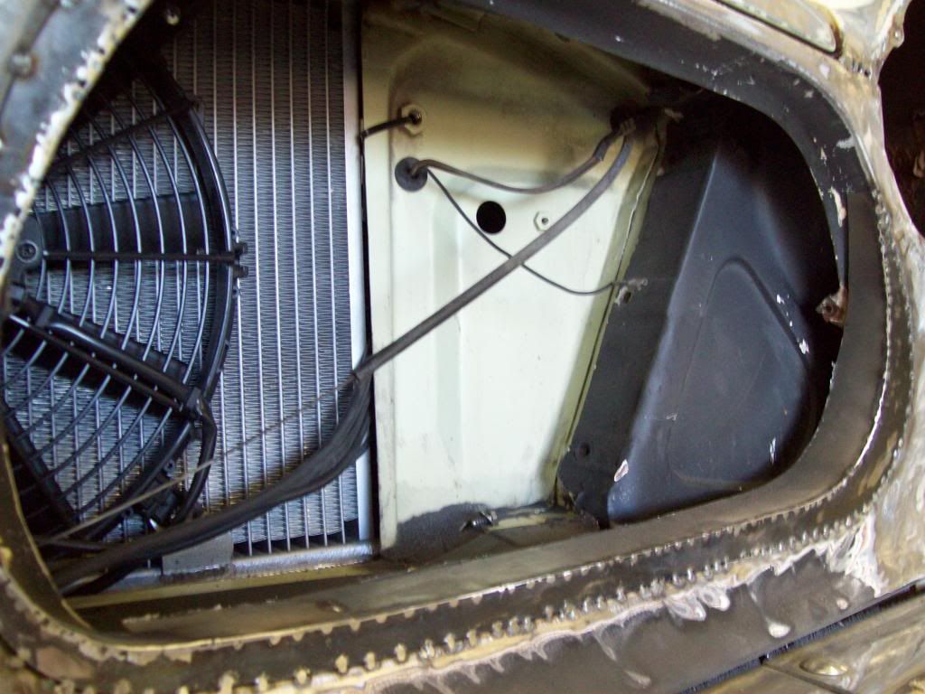
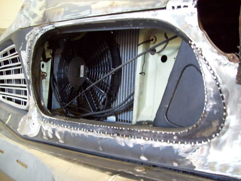
I am working out the final routing for the air intake, so I can order all the aluminum joints. As I said before, I cannot remove the old cal vent/heater duct, because the body vin number is actually stamped on it.. I removed the firewall attachment ring from the old heater box, becauses it is attached with a rubber/foam gasket between it and the firewall, so it should allow for motor torque/flex. I build the filter box on top of the factory attachement ring, because it has a water resevoir and drain made into it, The shape of the filter box provides a function with the water draining, while looking somewhat recognizable as a Volvo feature.
There will be identical aluminum runners on each side, so that should make everyting look even.. I have found a company that extrudes aluminum sheets with a fin pattern in it, and I was think about making a curved intake cover that will be welded into the insides of both runners, so it would have an appearance of a engine cover.
I am sure it isnt too easy to see what is going on here, but I really think will come together as a nice package, once all the components are put in place and finished out..
Pictured also, is the Swedish Ops direct bolt LS Conversion radiator manufactured for us by DeWitts....


Leave a comment:
Leave a comment: