 Tweet
Tweet
Alright, picking up where we left off somewhat.
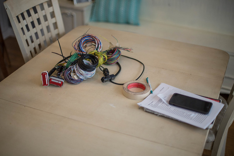
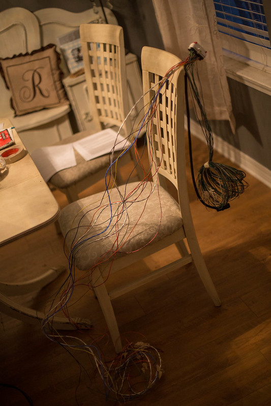
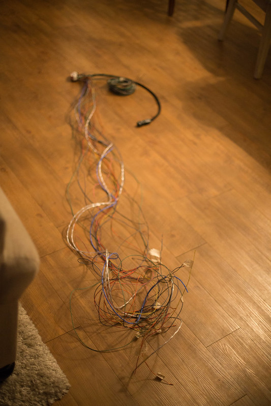
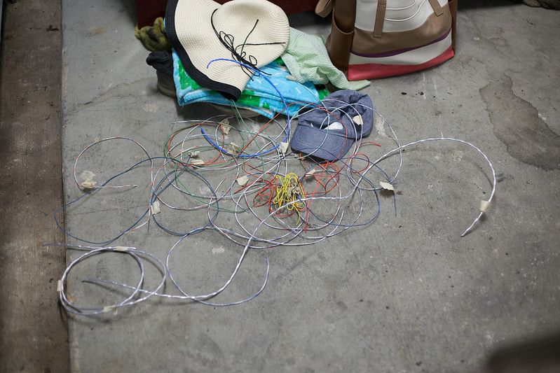
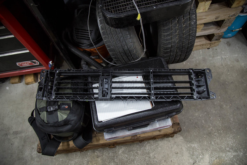
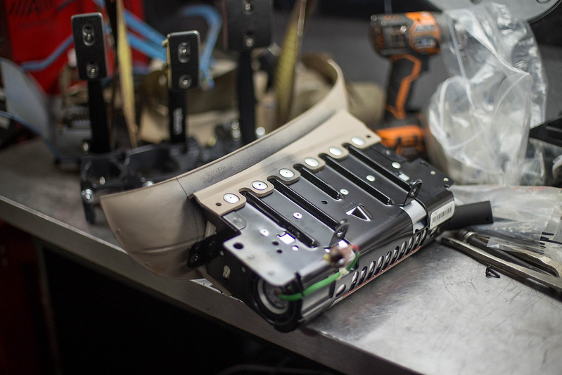
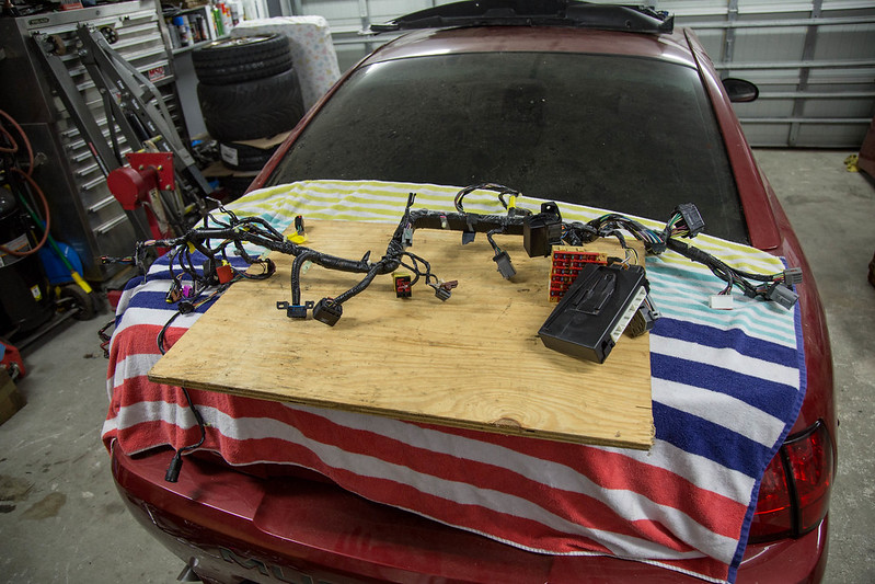
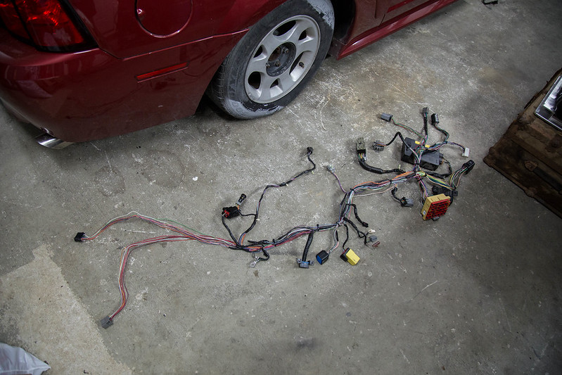
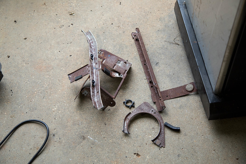
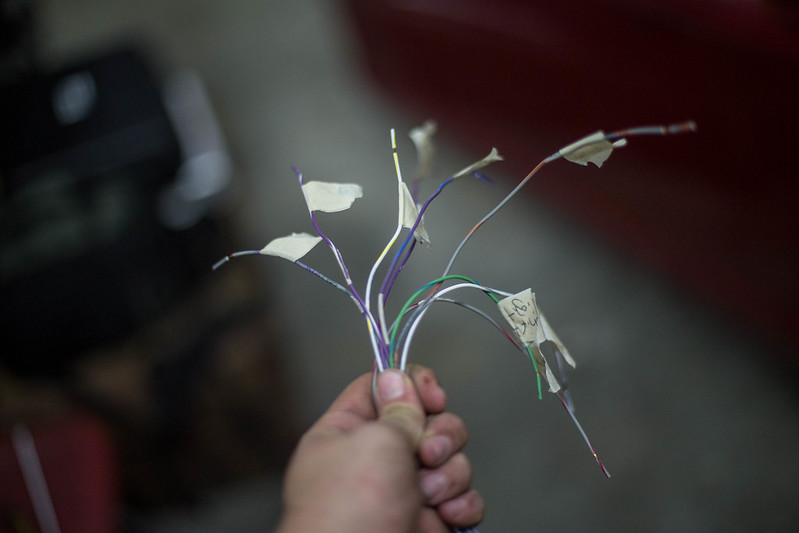
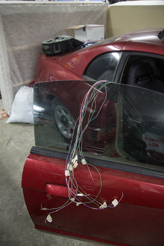
Started working on the ms3pro harness. Pulled it inside, pages out of the manual in hand and started sorting through the wires. I had previously grouped all the specific type of wires together, analog inputs together, injectors, ignition, etc etc to make it a bit easier when I got this point.
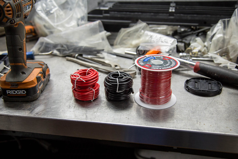
Keep in mind. This is my first time ever building an engine harness. Ive done a few smal harness stuff here and there for headlights etc, but nothing like this. Still trying to figure out whats the best process and way to do this. Im still missing a few key components that help figure out exact wire length needed and whatnot, but those will come in time. I promise even tho all these pictures look the same progress is being made.... I hope.
 new computer (1 of 18)-2 by lawrx, on Flickr
 new computer (2 of 18)-2 by lawrx, on Flickr
 new computer (3 of 18)-2 by lawrx, on Flickr
 new computer (4 of 18)-2 by lawrx, on Flickr
 new computer (5 of 18)-2 by lawrx, on Flickr
 new computer (6 of 18)-2 by lawrx, on Flickr
 new computer (7 of 18)-2 by lawrx, on Flickr
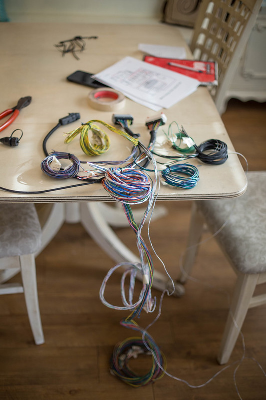
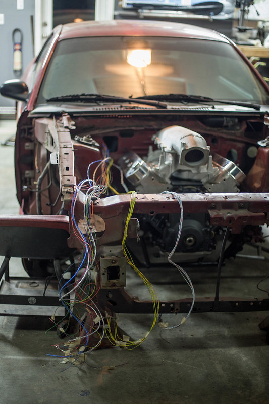
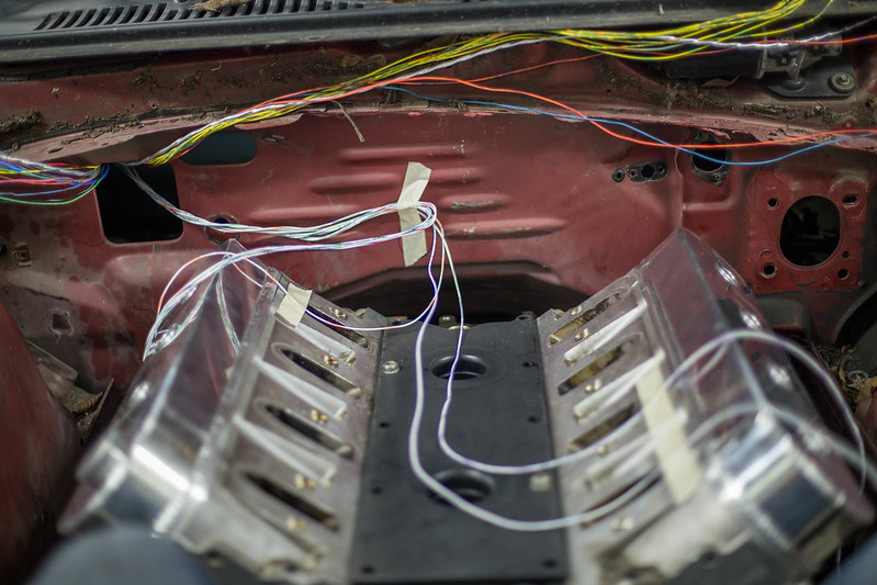
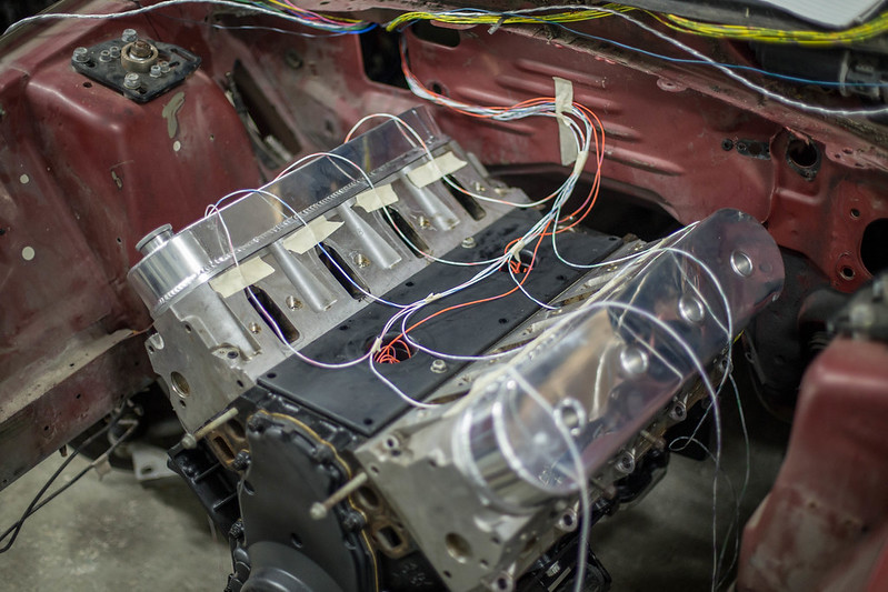
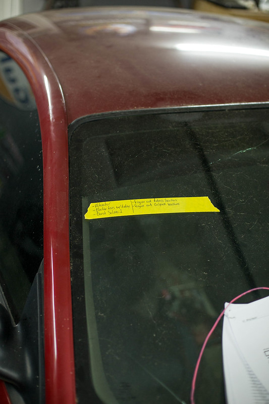
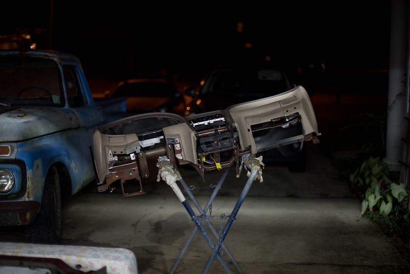
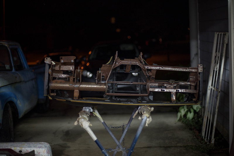
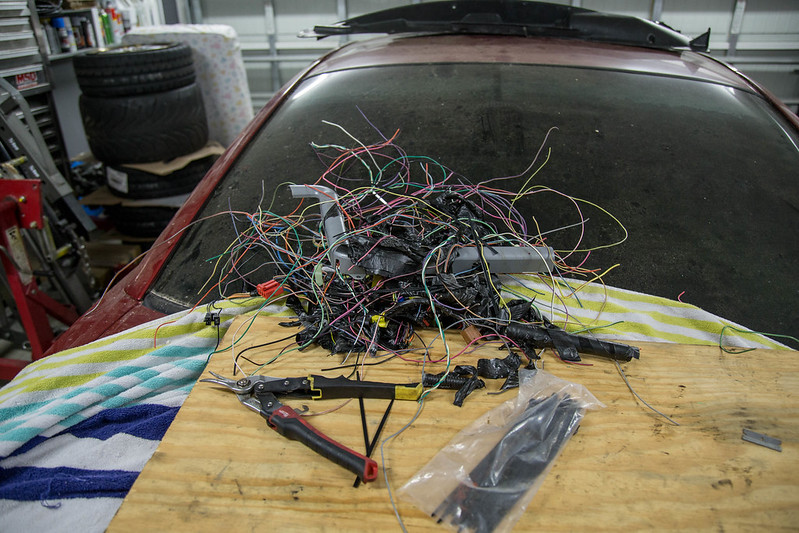
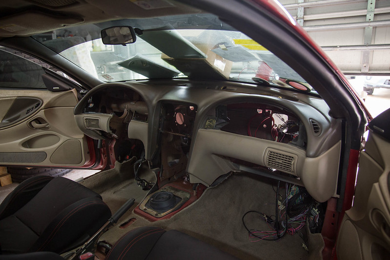
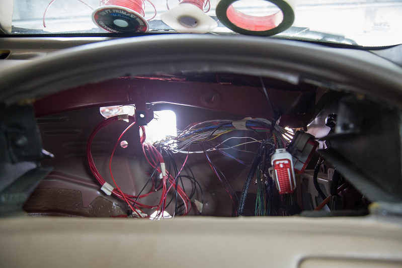
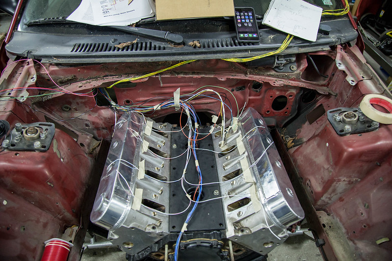
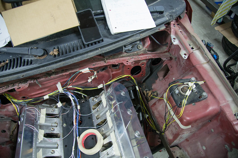
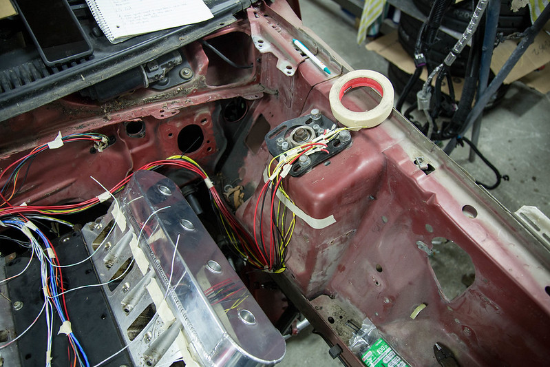
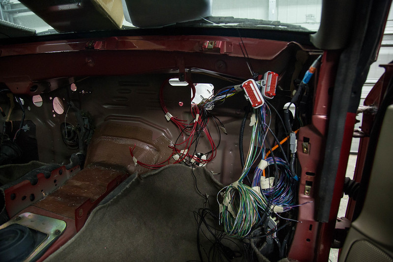
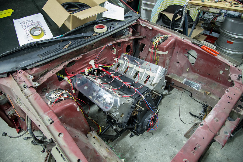
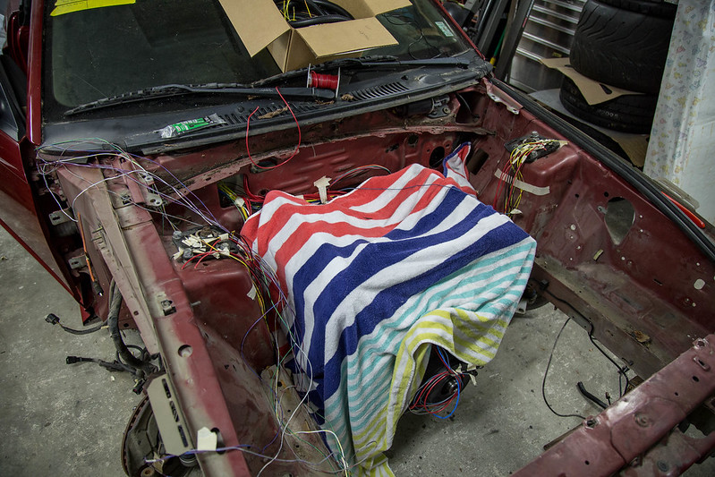
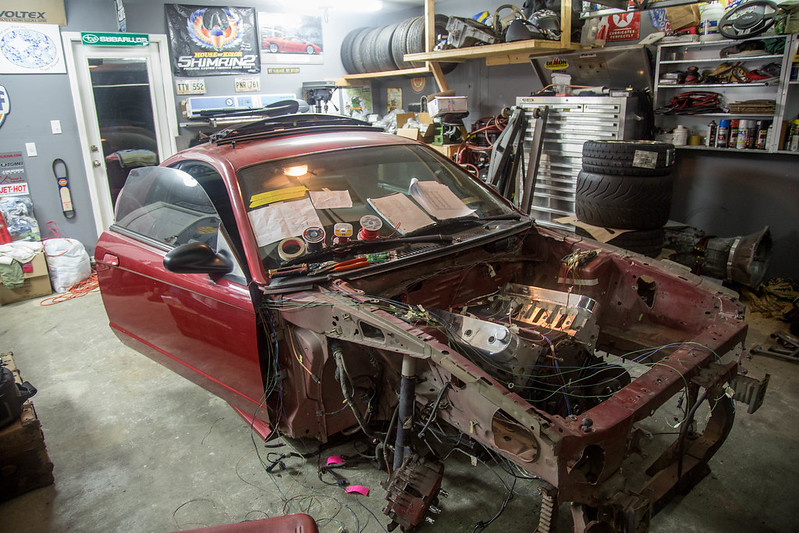
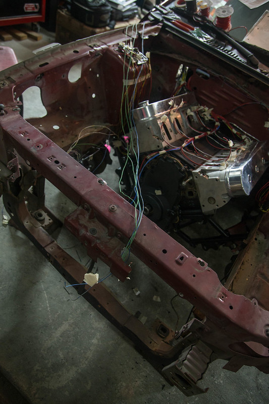
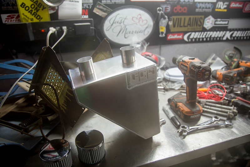
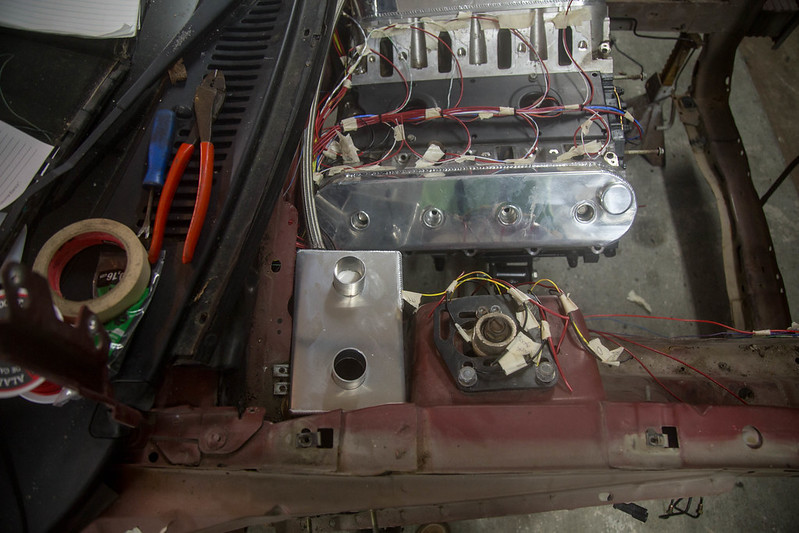
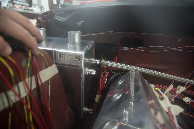
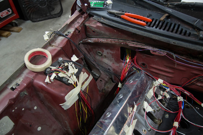
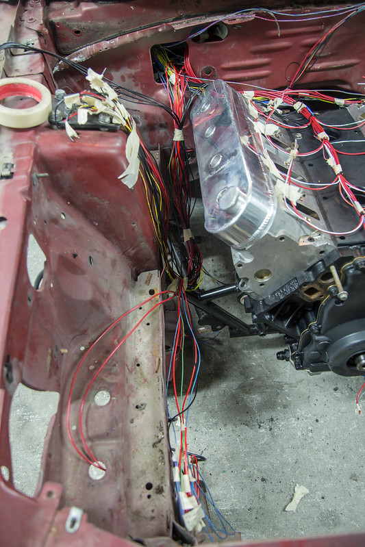
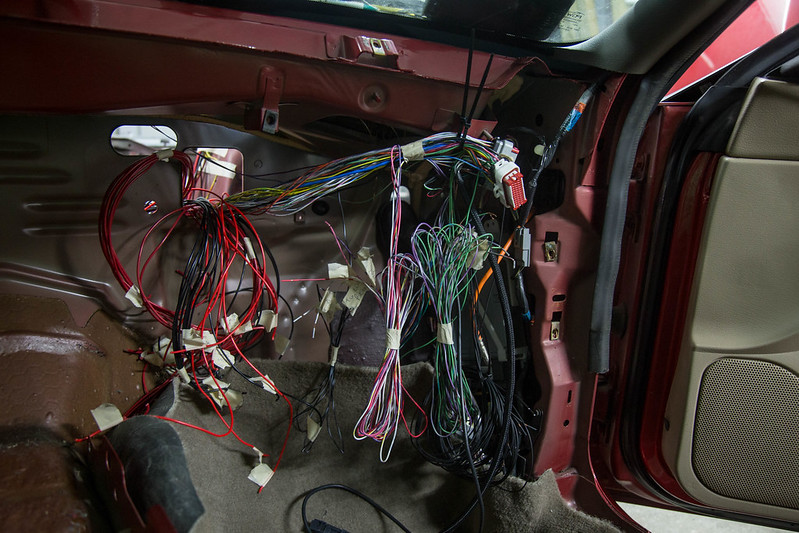
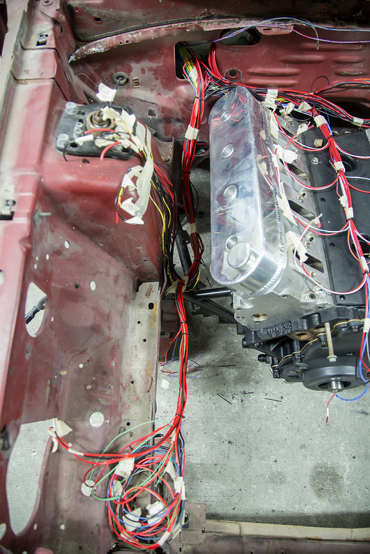
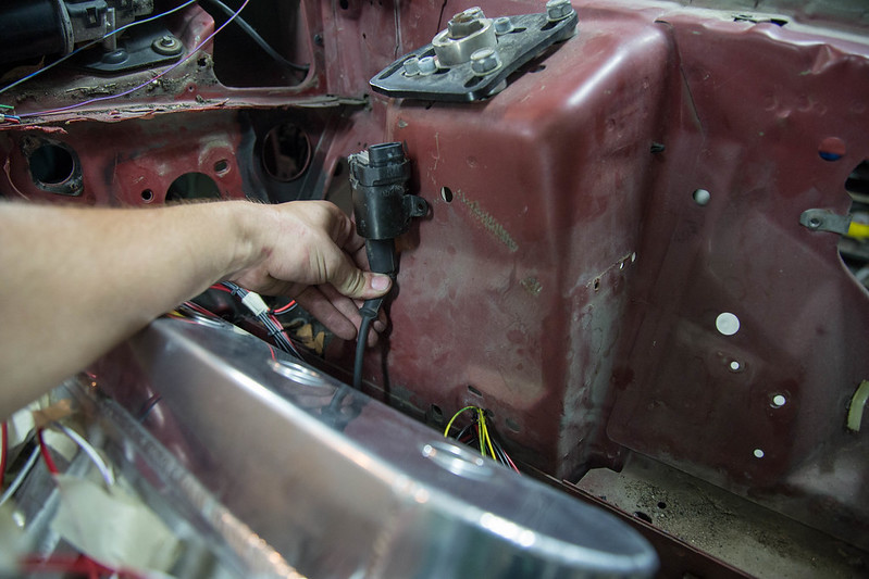
With wires sorted, labels, grouped together etc it was time to bring it to the car and start laying it out. The ecu itself will be mounted just behind the glovebox for easy access incase it needs accessing. I tie strapped the plug there and started fishing the wires through. Initially I was going to run the harness through the firewall directly behind the intake manifold. But upon mocking it up, the harness will be too big and bulky and simply be too crammed in that tight space. So I will be using the large open area from the ac setup. Once its welded up ill be putting my plug there. It will be somewhat hidden as my catch can setup will be mounted in that little corner area between the firewall and the strut tower.
 new computer (8 of 18)-2 by lawrx, on Flickr
 new computer (9 of 18)-2 by lawrx, on Flickr
 new computer (10 of 18)-2 by lawrx, on Flickr
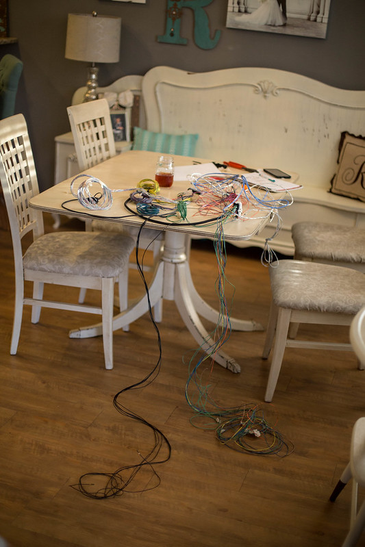
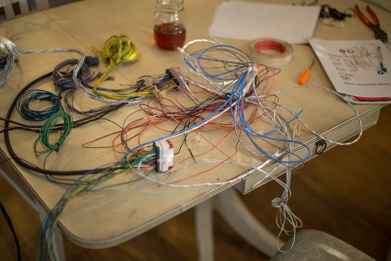
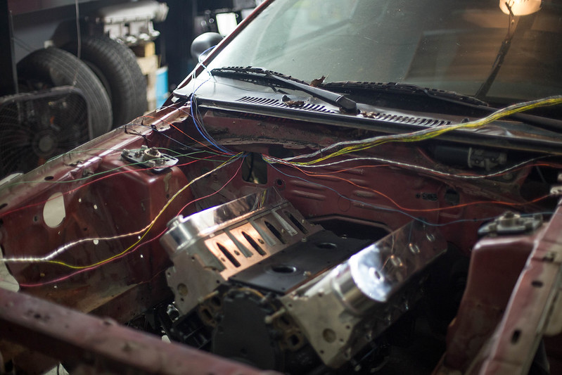
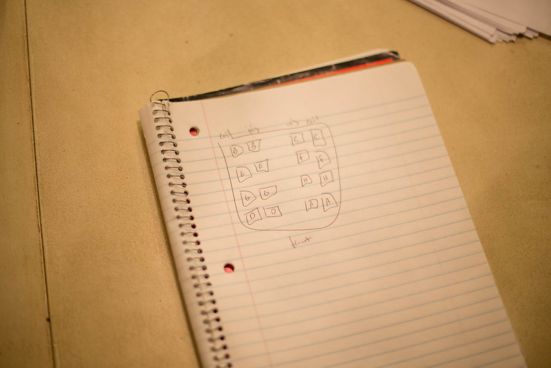
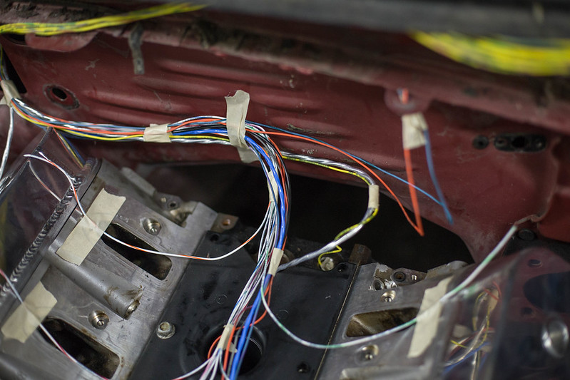
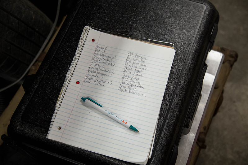
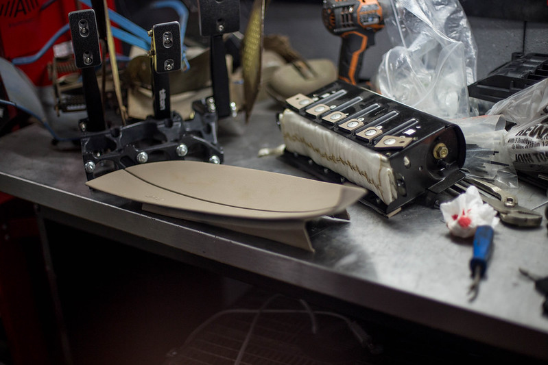
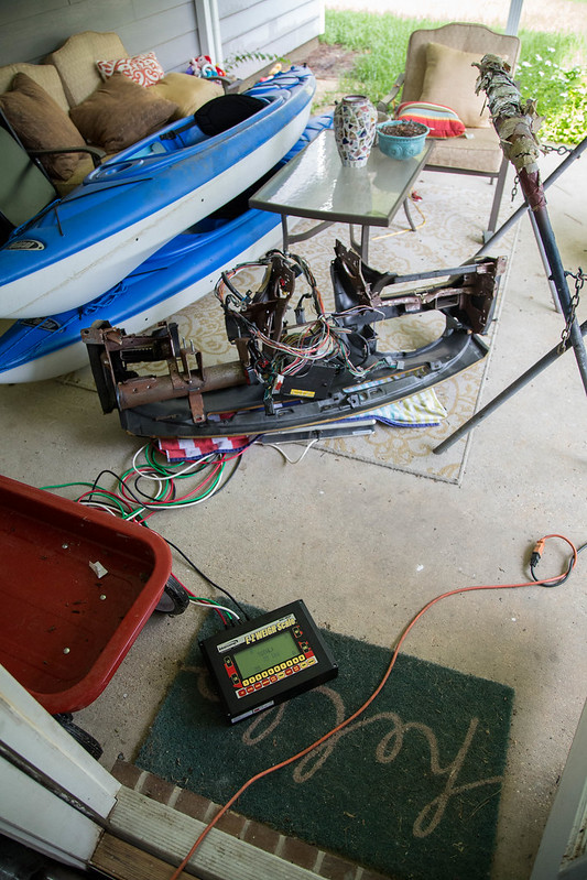
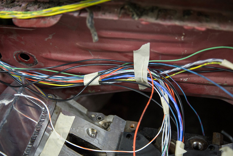
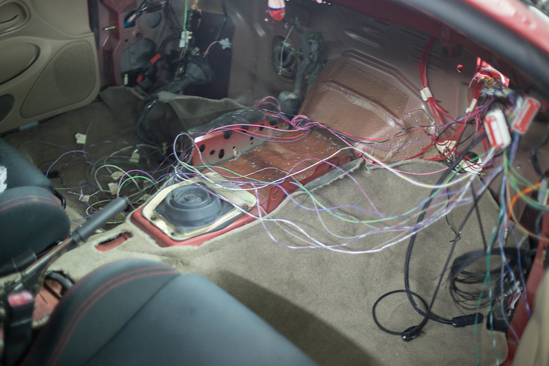
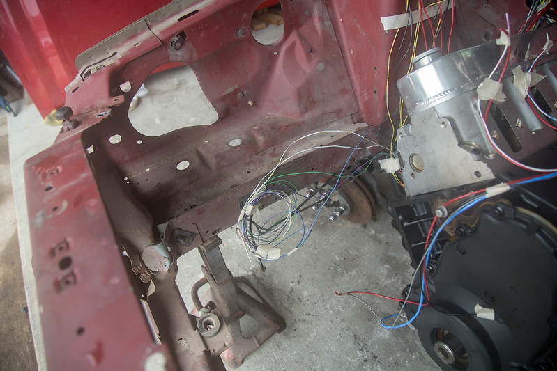
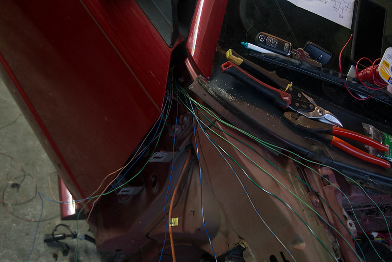
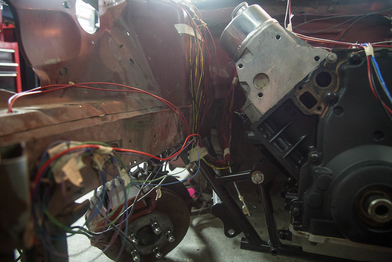
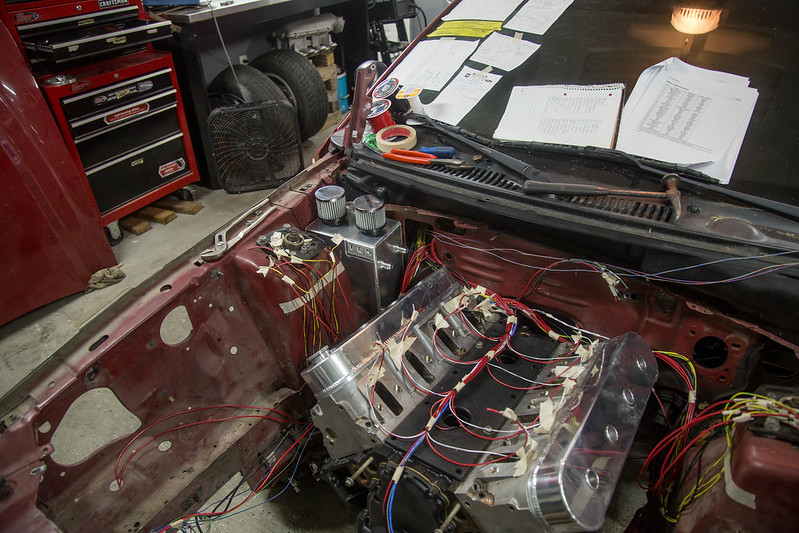
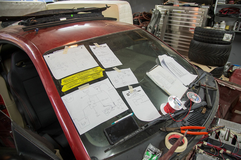
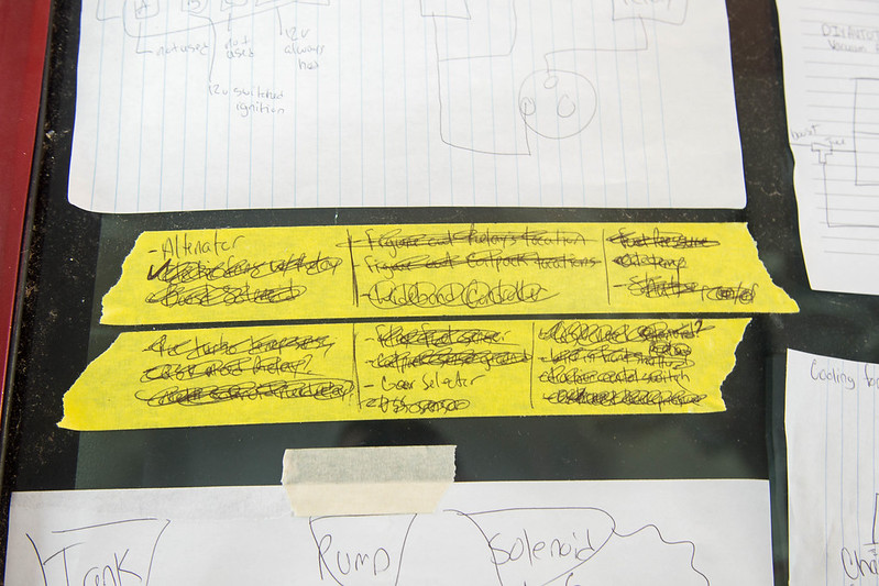
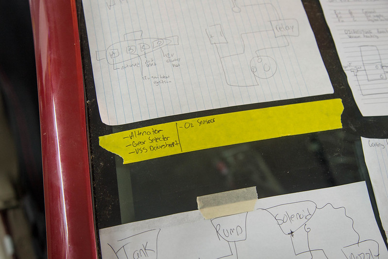
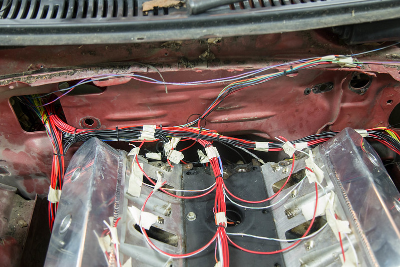
Once the ECU, firewall thru placement finalized and the harness ready to be strung out everywhere, I sat down and went through the manual to start drawing the few diagrams I would need to reference during the wiring process. this would make it easier as they would all be own one place in my notebook vs spread out over the manual on multiple pages. After that it was time to start stringing out the harness for lengths and routing. currently im running the signal wires that all go to the ecu. Once all routing and locations are finalized ill add in the 12v and sensor ground wires that all tie in to each other.
 new computer (11 of 18)-2 by lawrx, on Flickr
 new computer (12 of 18)-2 by lawrx, on Flickr
 new computer (15 of 18)-2 by lawrx, on Flickr
 new computer (13 of 18)-2 by lawrx, on Flickr
 new computer (14 of 18)-2 by lawrx, on Flickr
 new computer (16 of 18)-2 by lawrx, on Flickr
 new computer (17 of 18)-2 by lawrx, on Flickr
 new computer (18 of 18)-2 by lawrx, on Flickr
Started working on the ms3pro harness. Pulled it inside, pages out of the manual in hand and started sorting through the wires. I had previously grouped all the specific type of wires together, analog inputs together, injectors, ignition, etc etc to make it a bit easier when I got this point.
Keep in mind. This is my first time ever building an engine harness. Ive done a few smal harness stuff here and there for headlights etc, but nothing like this. Still trying to figure out whats the best process and way to do this. Im still missing a few key components that help figure out exact wire length needed and whatnot, but those will come in time. I promise even tho all these pictures look the same progress is being made.... I hope.
new computer (1 of 18)-2 by lawrx, on Flickrnew computer (2 of 18)-2 by lawrx, on Flickrnew computer (3 of 18)-2 by lawrx, on Flickrnew computer (4 of 18)-2 by lawrx, on Flickrnew computer (5 of 18)-2 by lawrx, on Flickrnew computer (6 of 18)-2 by lawrx, on Flickrnew computer (7 of 18)-2 by lawrx, on FlickrWith wires sorted, labels, grouped together etc it was time to bring it to the car and start laying it out. The ecu itself will be mounted just behind the glovebox for easy access incase it needs accessing. I tie strapped the plug there and started fishing the wires through. Initially I was going to run the harness through the firewall directly behind the intake manifold. But upon mocking it up, the harness will be too big and bulky and simply be too crammed in that tight space. So I will be using the large open area from the ac setup. Once its welded up ill be putting my plug there. It will be somewhat hidden as my catch can setup will be mounted in that little corner area between the firewall and the strut tower.
new computer (8 of 18)-2 by lawrx, on Flickrnew computer (9 of 18)-2 by lawrx, on Flickrnew computer (10 of 18)-2 by lawrx, on FlickrOnce the ECU, firewall thru placement finalized and the harness ready to be strung out everywhere, I sat down and went through the manual to start drawing the few diagrams I would need to reference during the wiring process. this would make it easier as they would all be own one place in my notebook vs spread out over the manual on multiple pages. After that it was time to start stringing out the harness for lengths and routing. currently im running the signal wires that all go to the ecu. Once all routing and locations are finalized ill add in the 12v and sensor ground wires that all tie in to each other.
new computer (11 of 18)-2 by lawrx, on Flickrnew computer (12 of 18)-2 by lawrx, on Flickrnew computer (15 of 18)-2 by lawrx, on Flickrnew computer (13 of 18)-2 by lawrx, on Flickrnew computer (14 of 18)-2 by lawrx, on Flickrnew computer (16 of 18)-2 by lawrx, on Flickrnew computer (17 of 18)-2 by lawrx, on Flickrnew computer (18 of 18)-2 by lawrx, on Flickr


Comment