Announcement

Collapse
No announcement yet.

Easy Slider z32 missile

Collapse
X
 
  • Filter
  • Time
  • Show
Clear All
new posts

  • EasySpeed*Inc
    replied
    Today's topic, hood pins


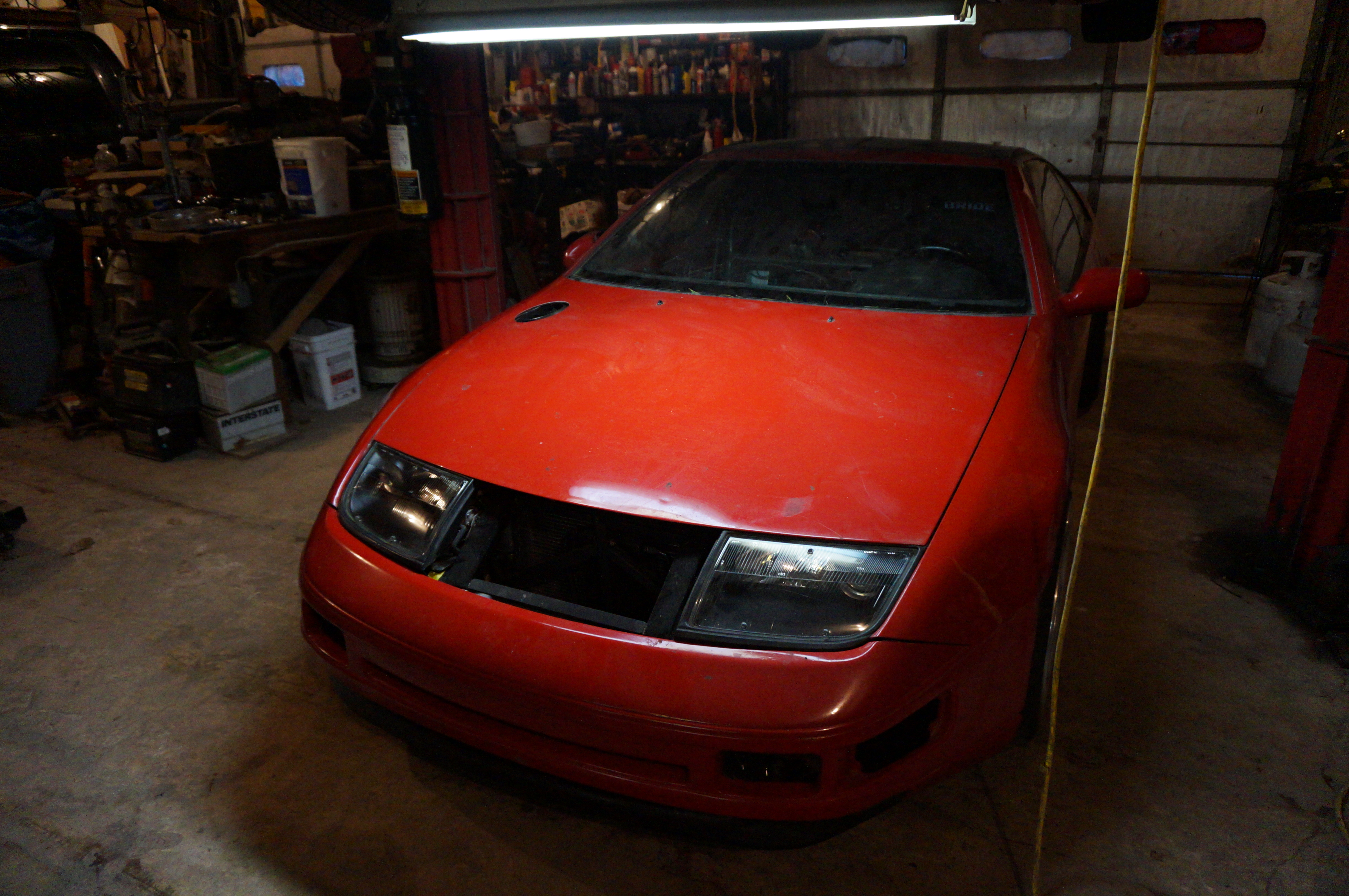
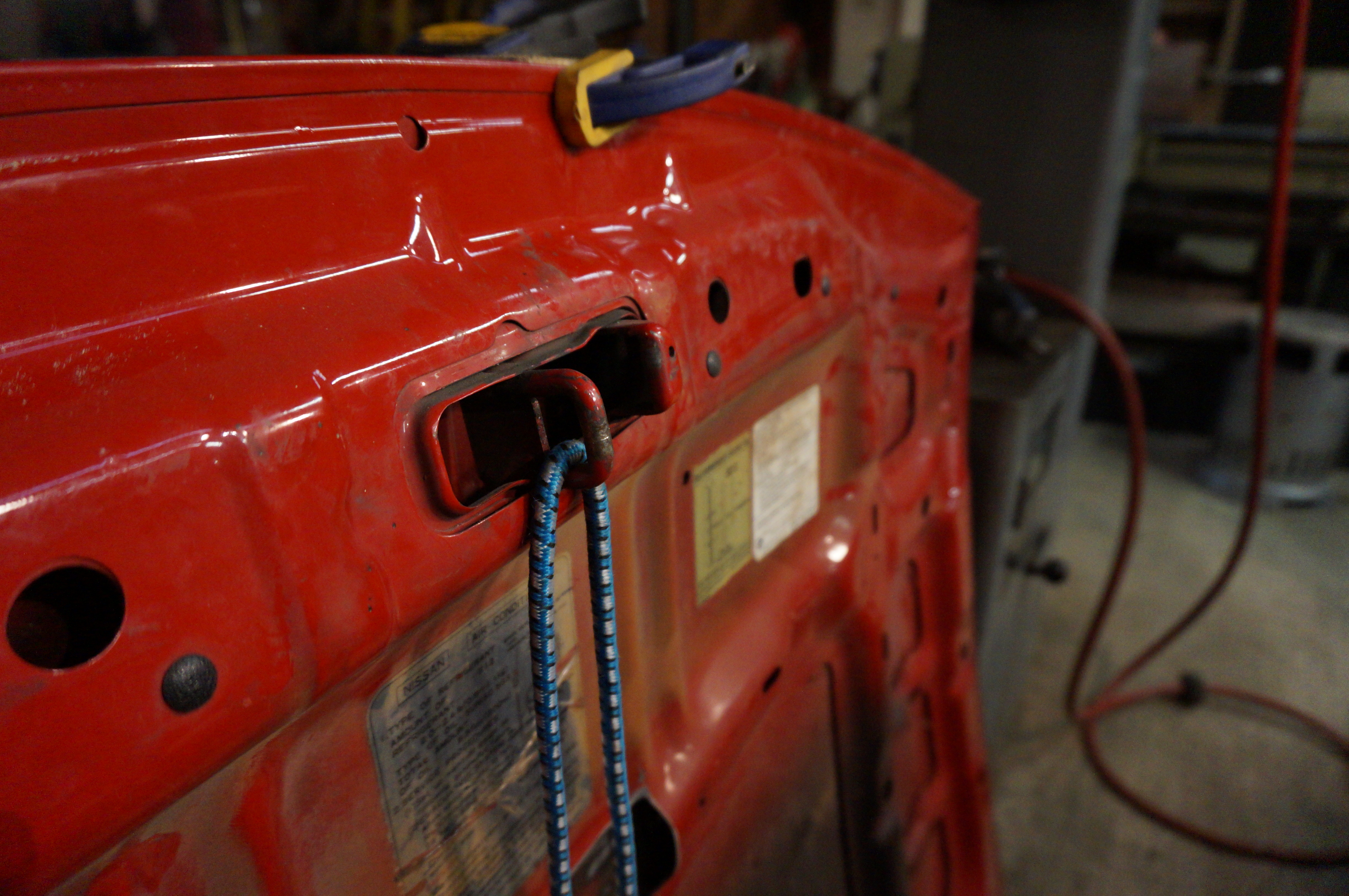
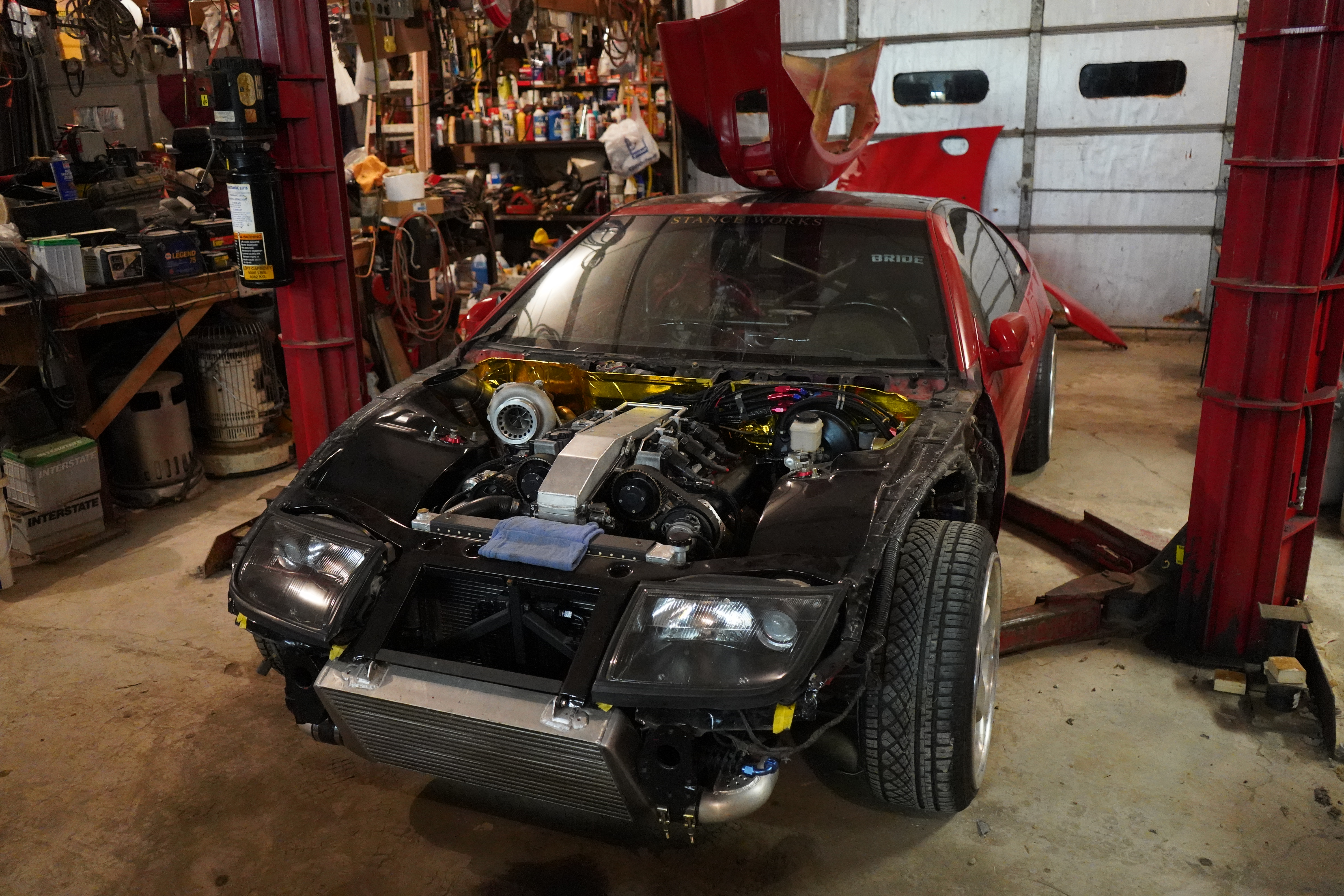
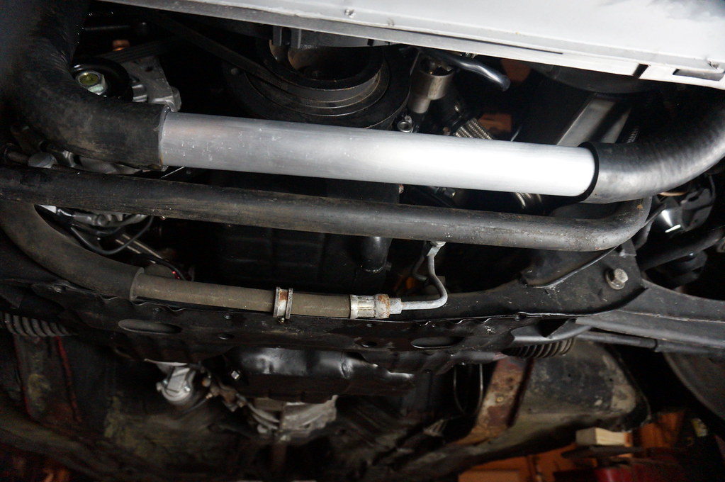
    Currently ditching the factory hood release


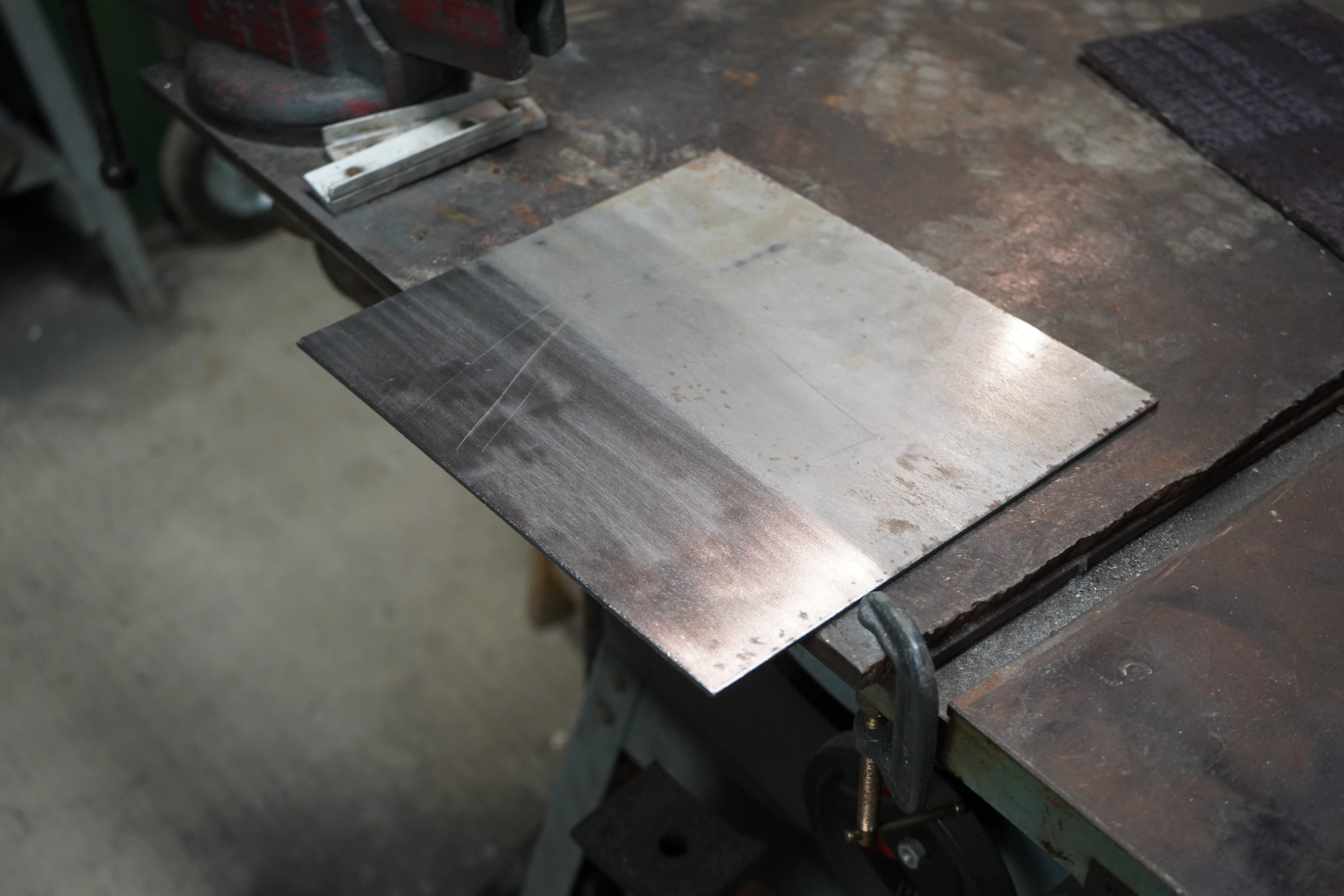
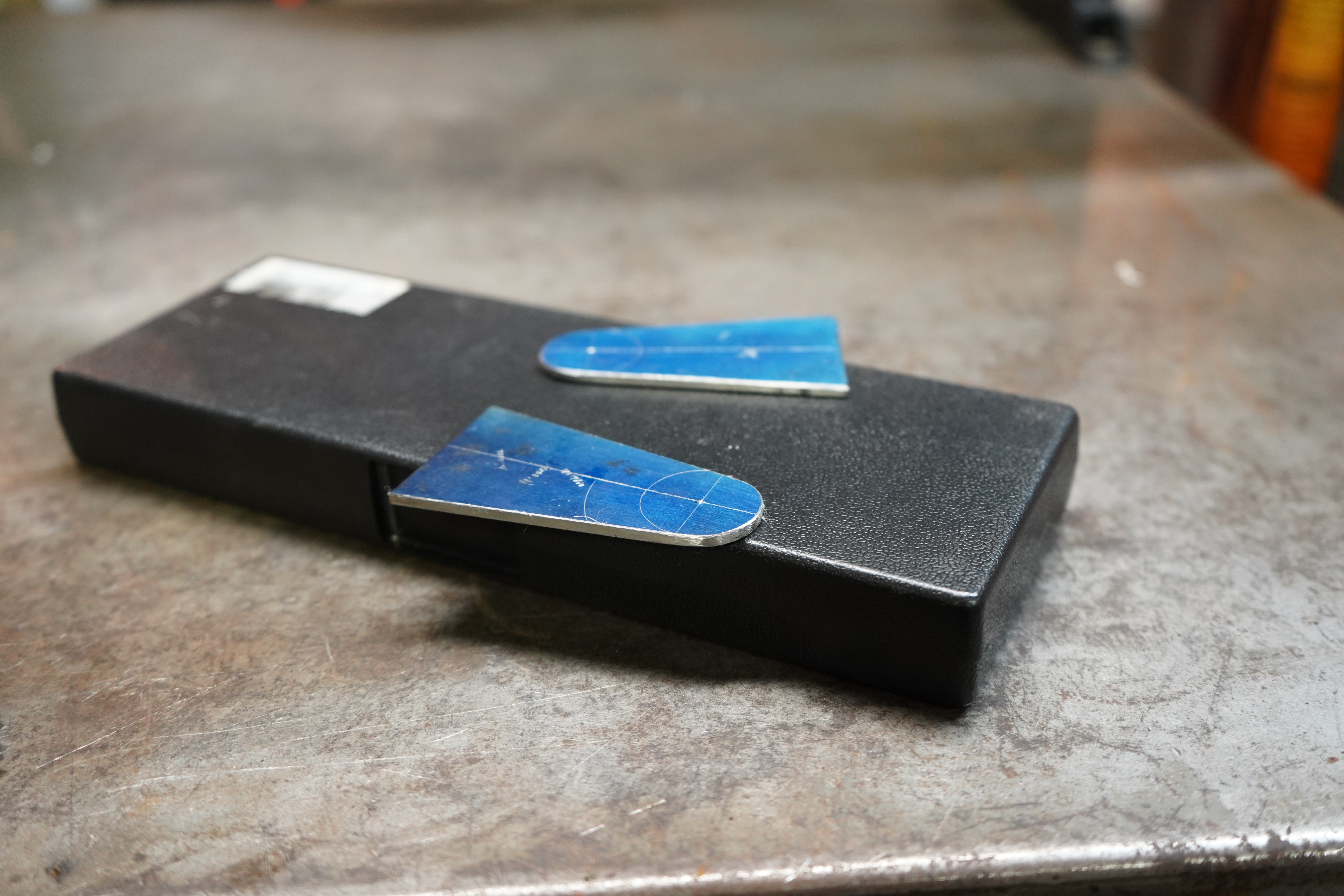
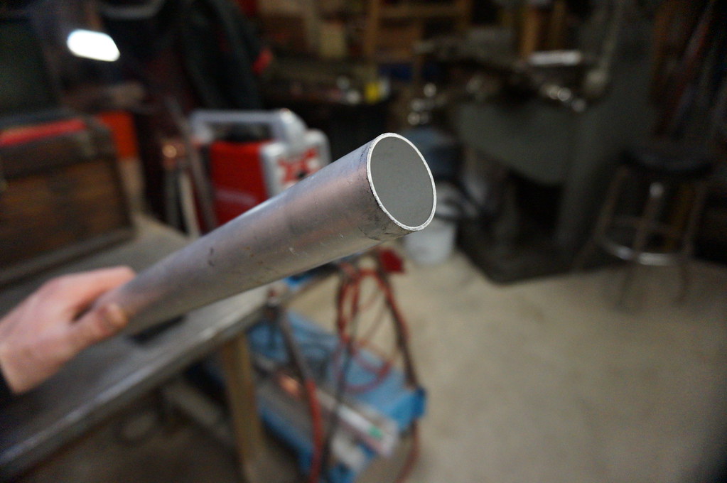
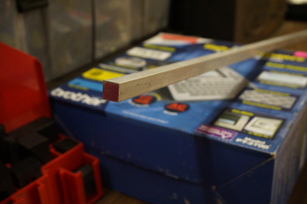
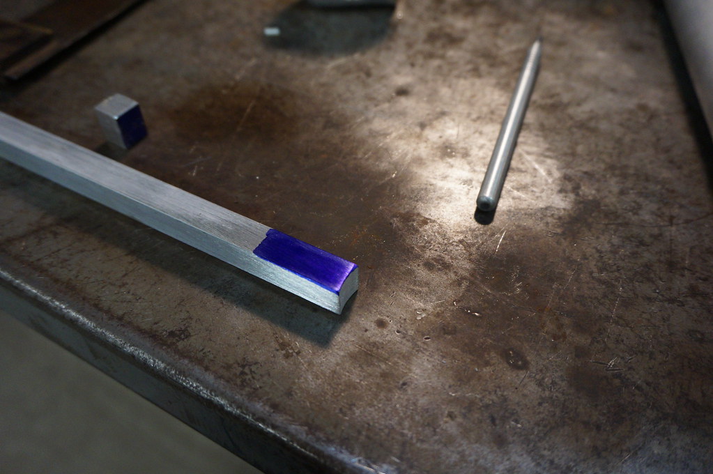
    As usual a nice chunk of aluminum to start with


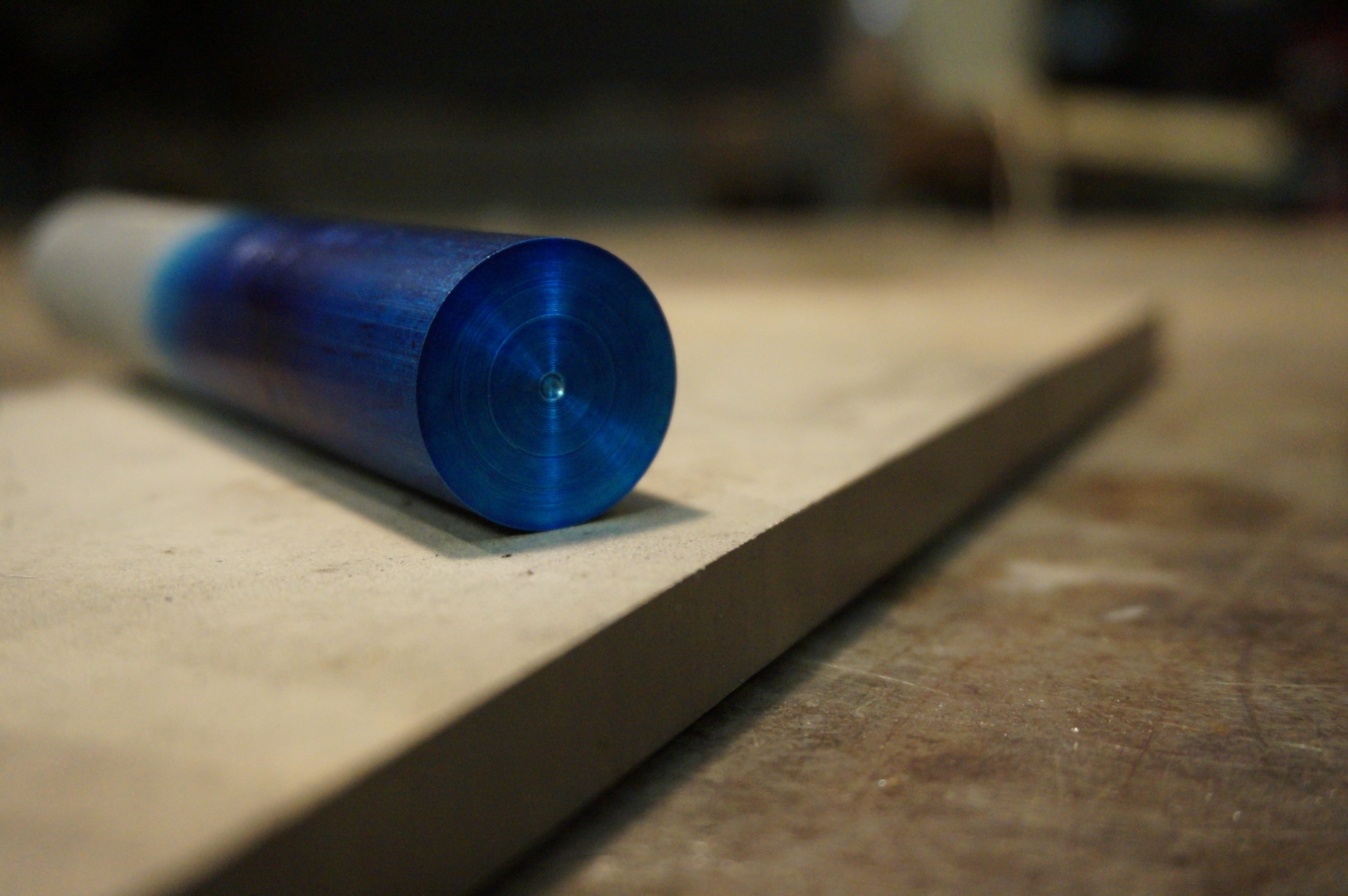
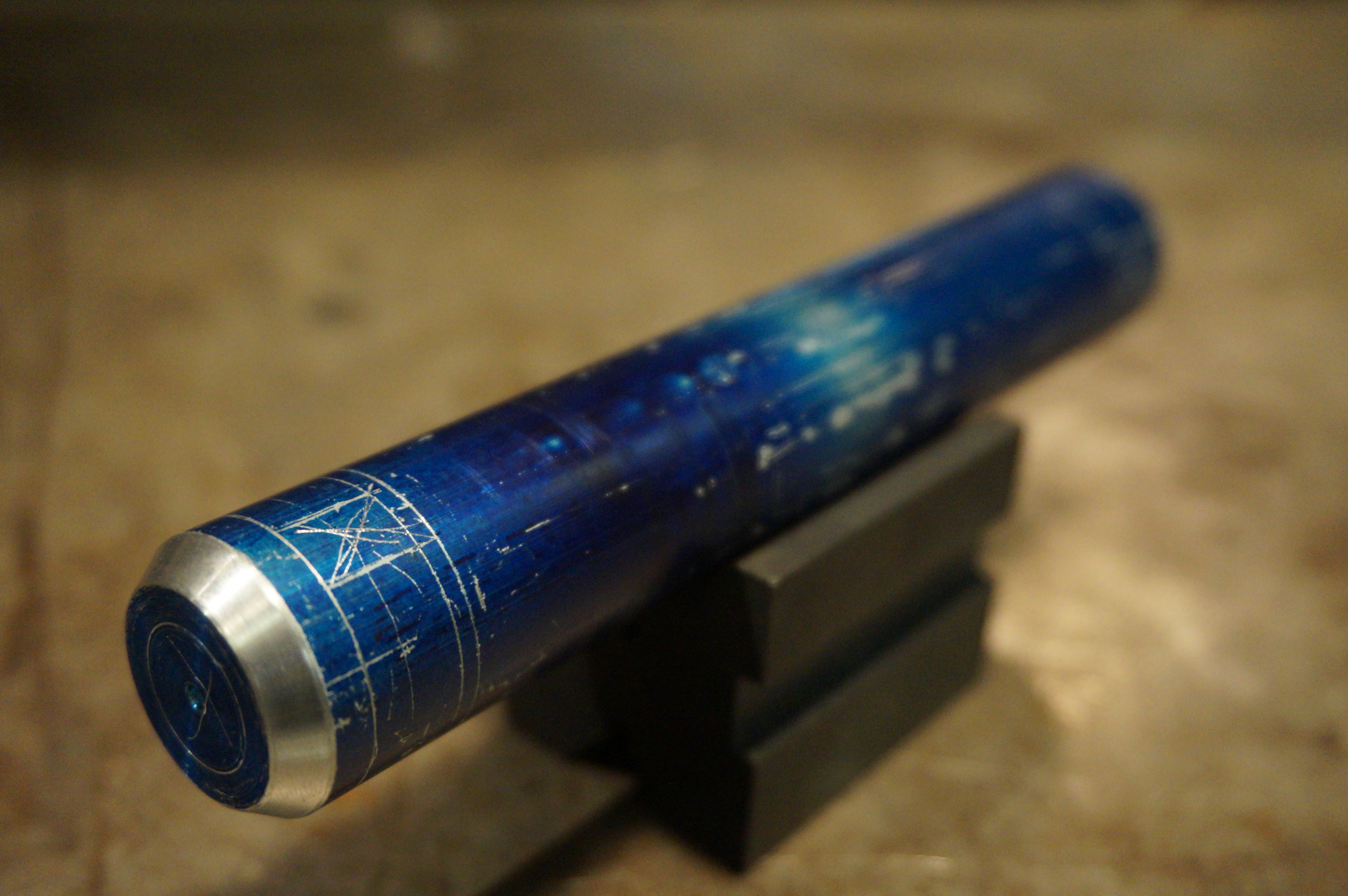
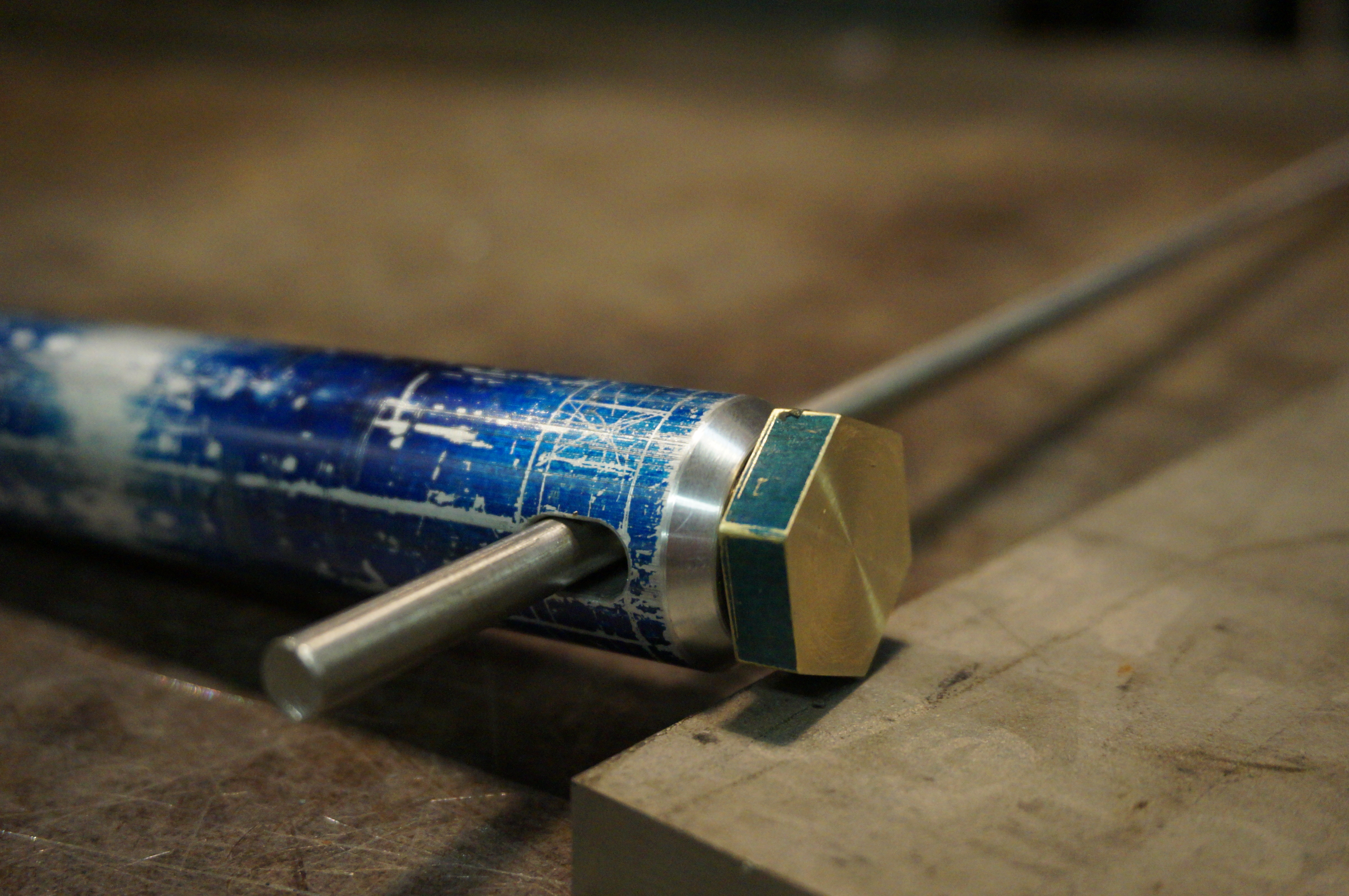
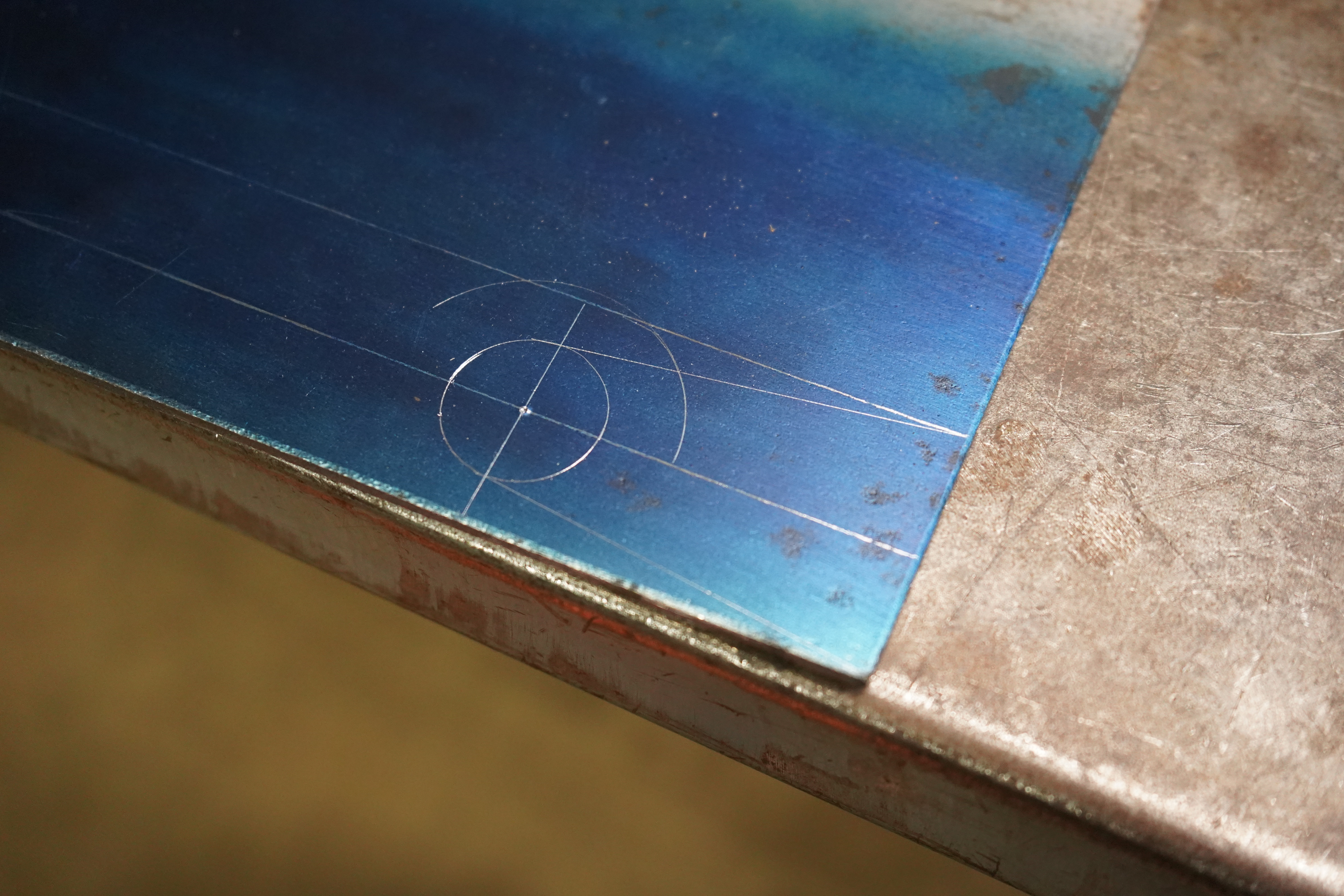
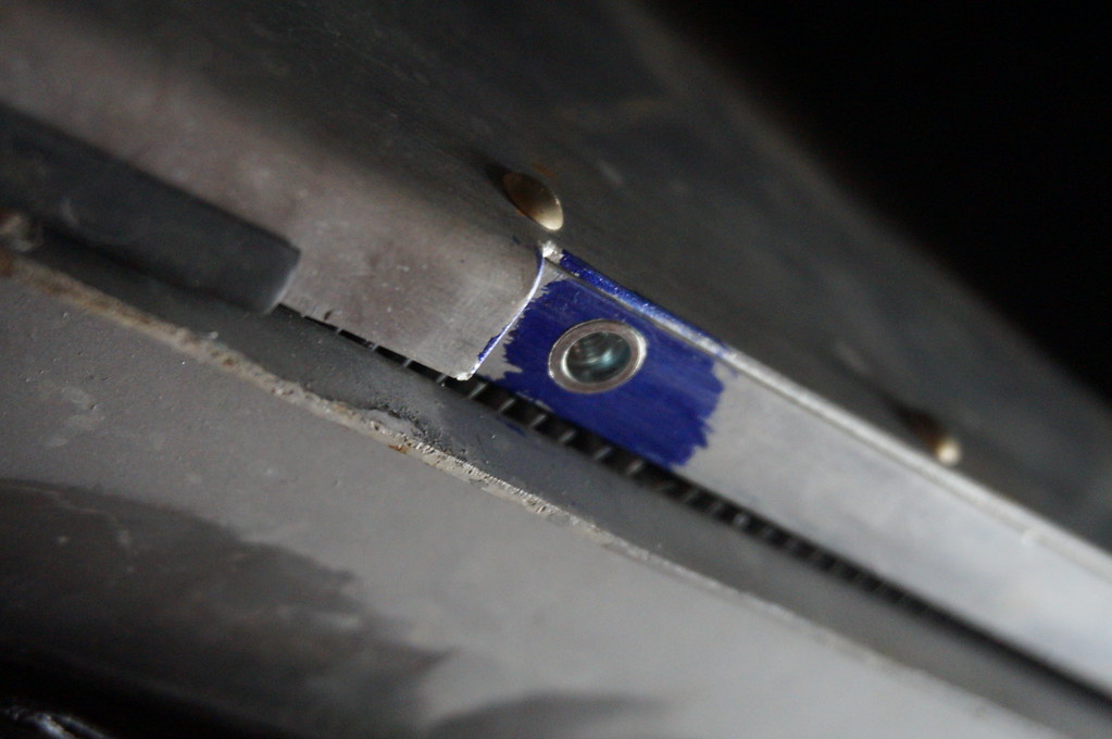
    Dykem looks so cool with just a bit of wear
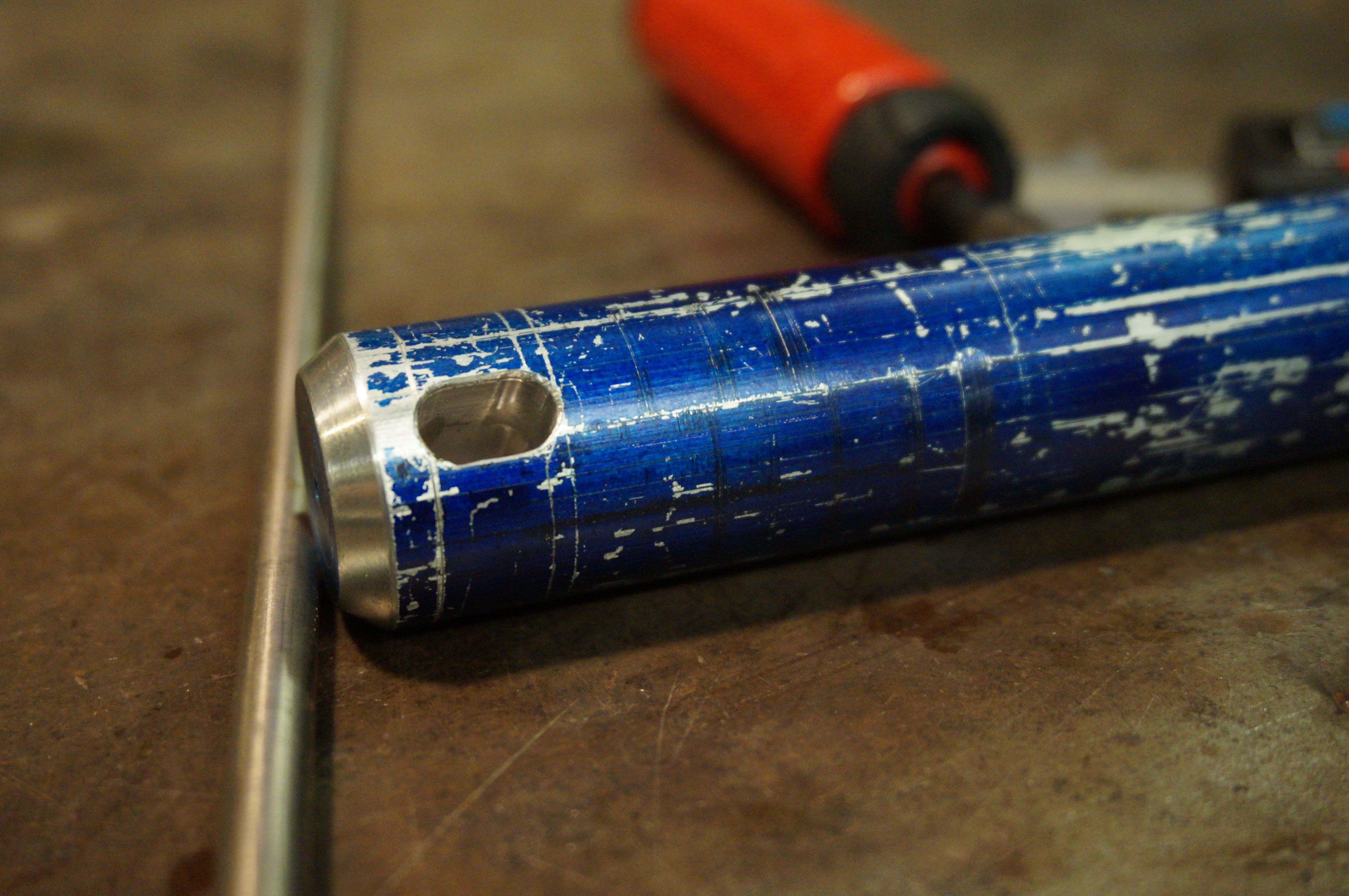
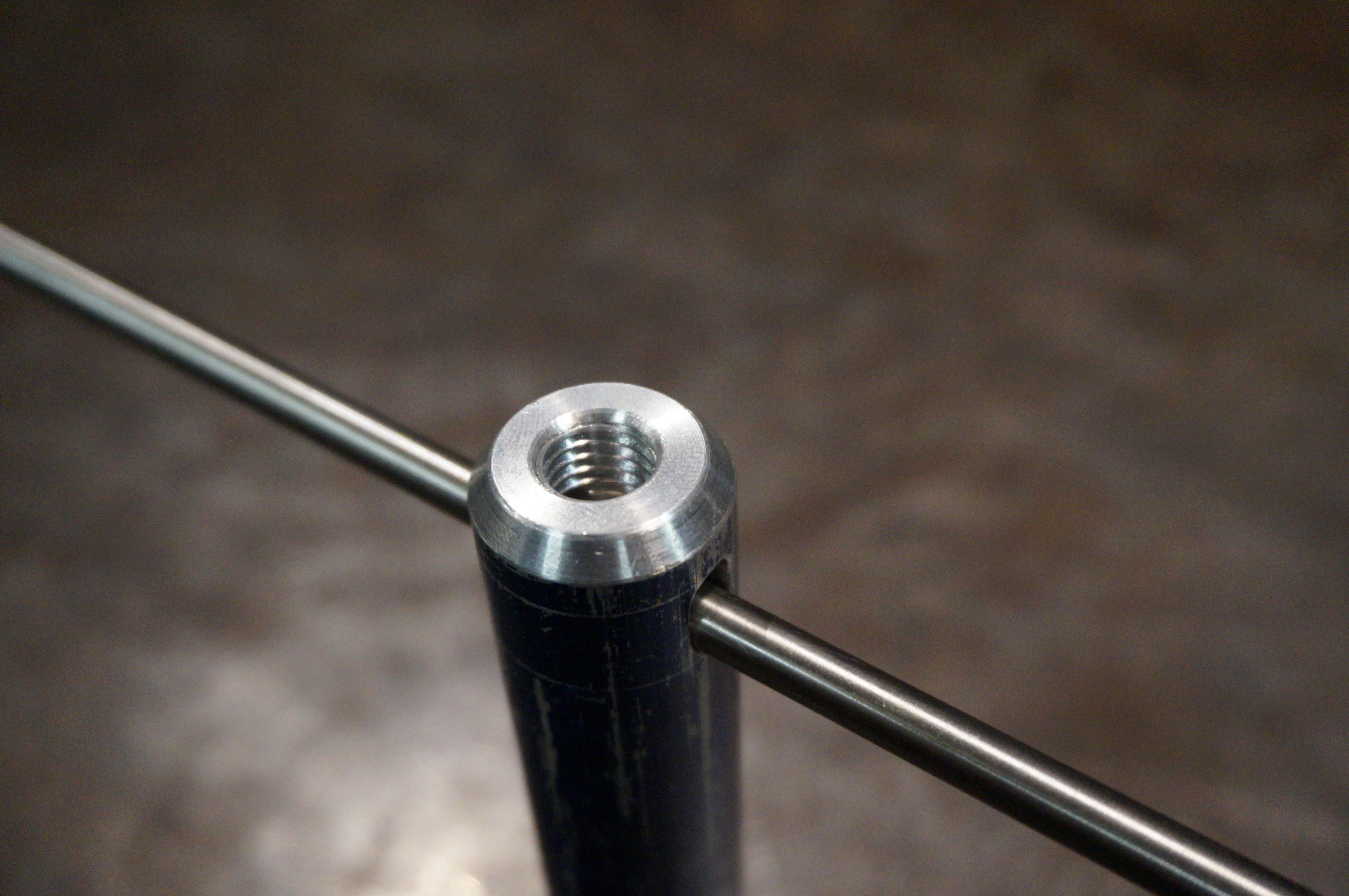
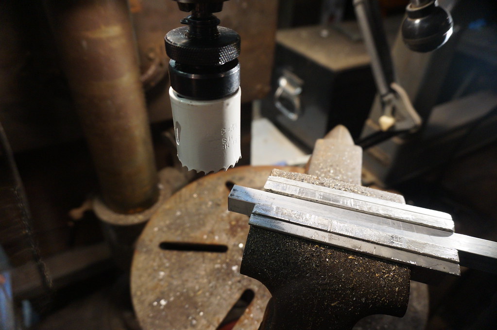
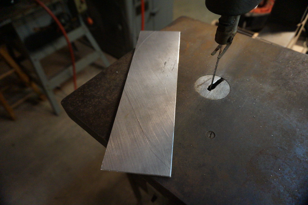


    Made a slot


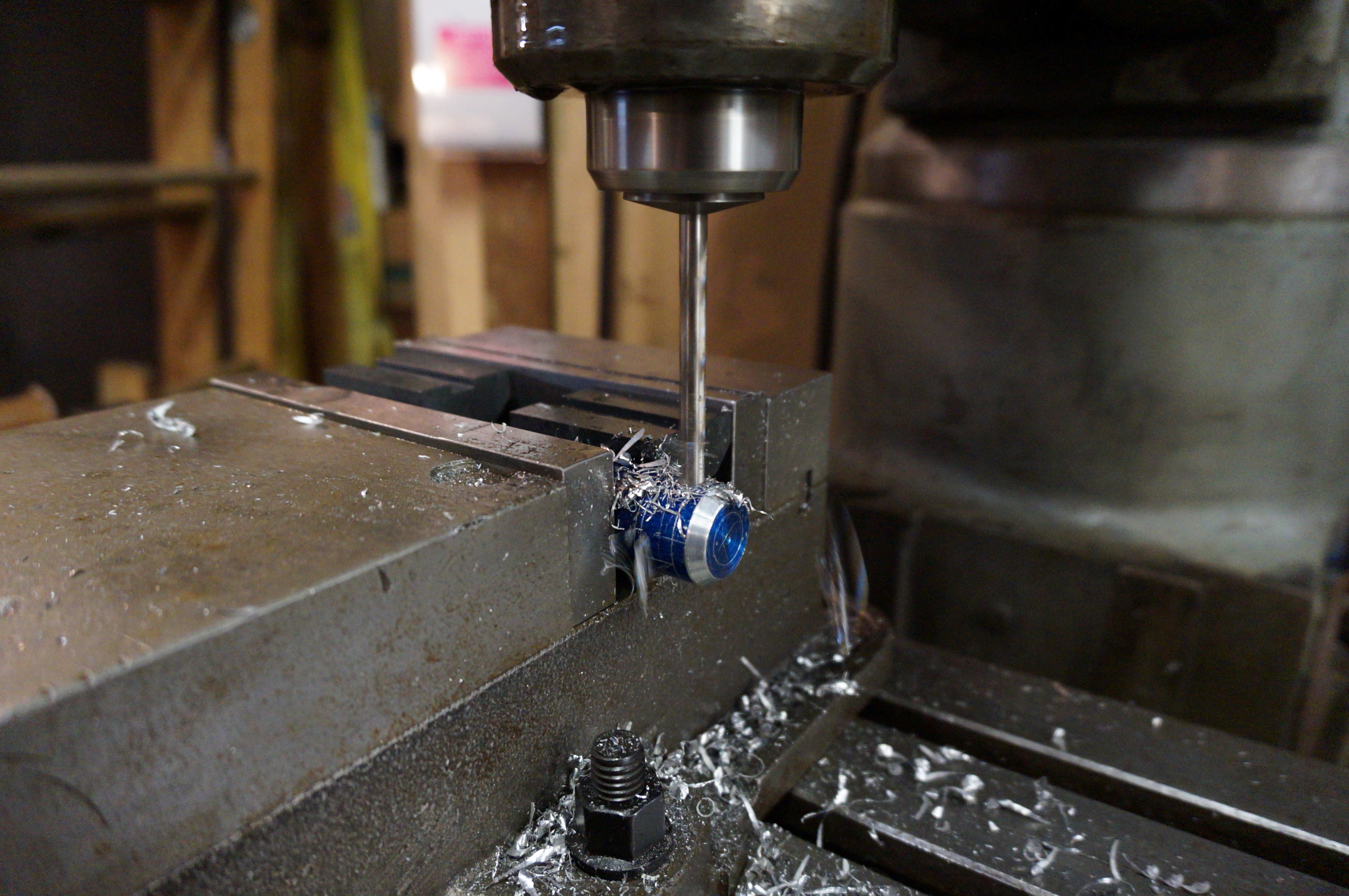
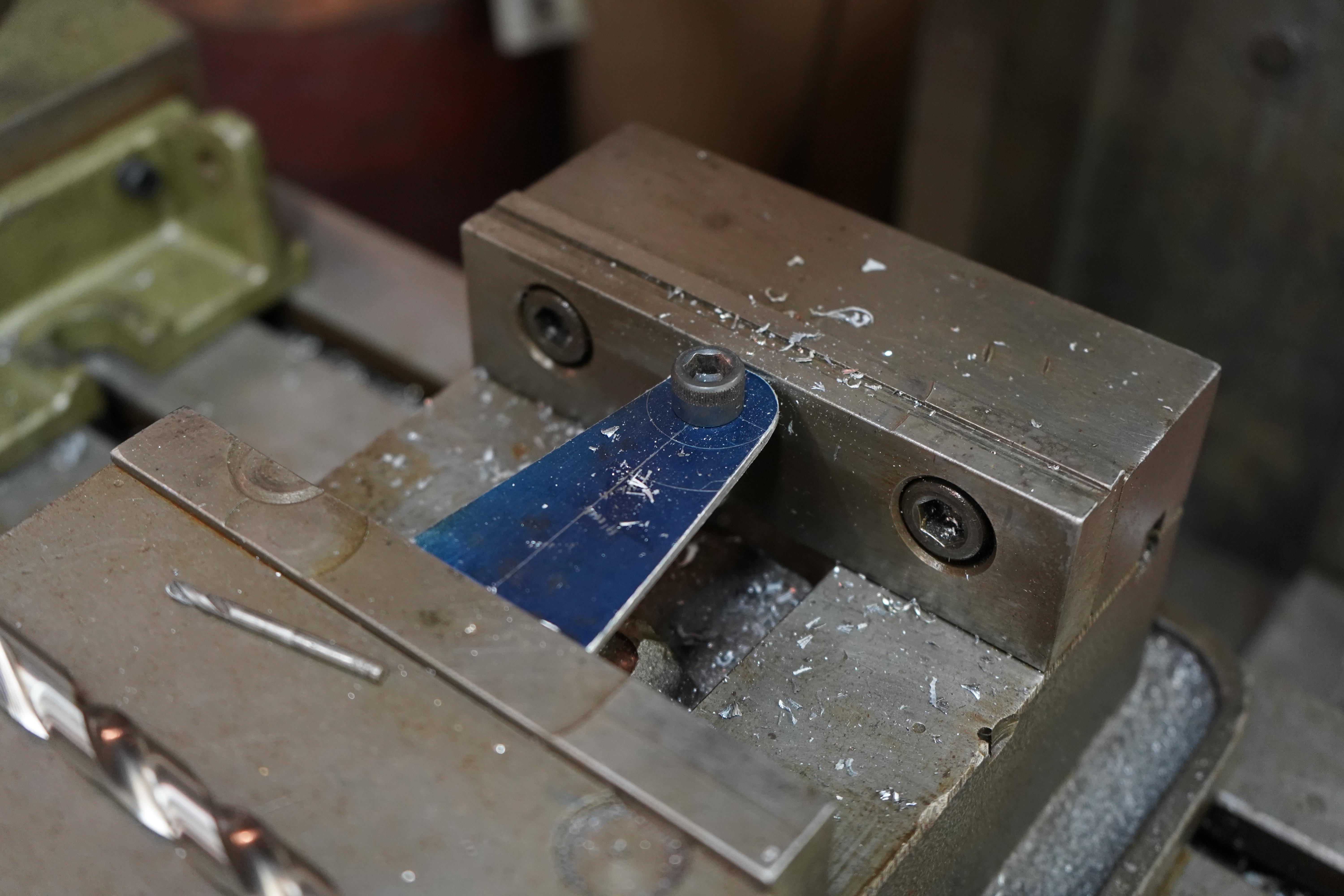
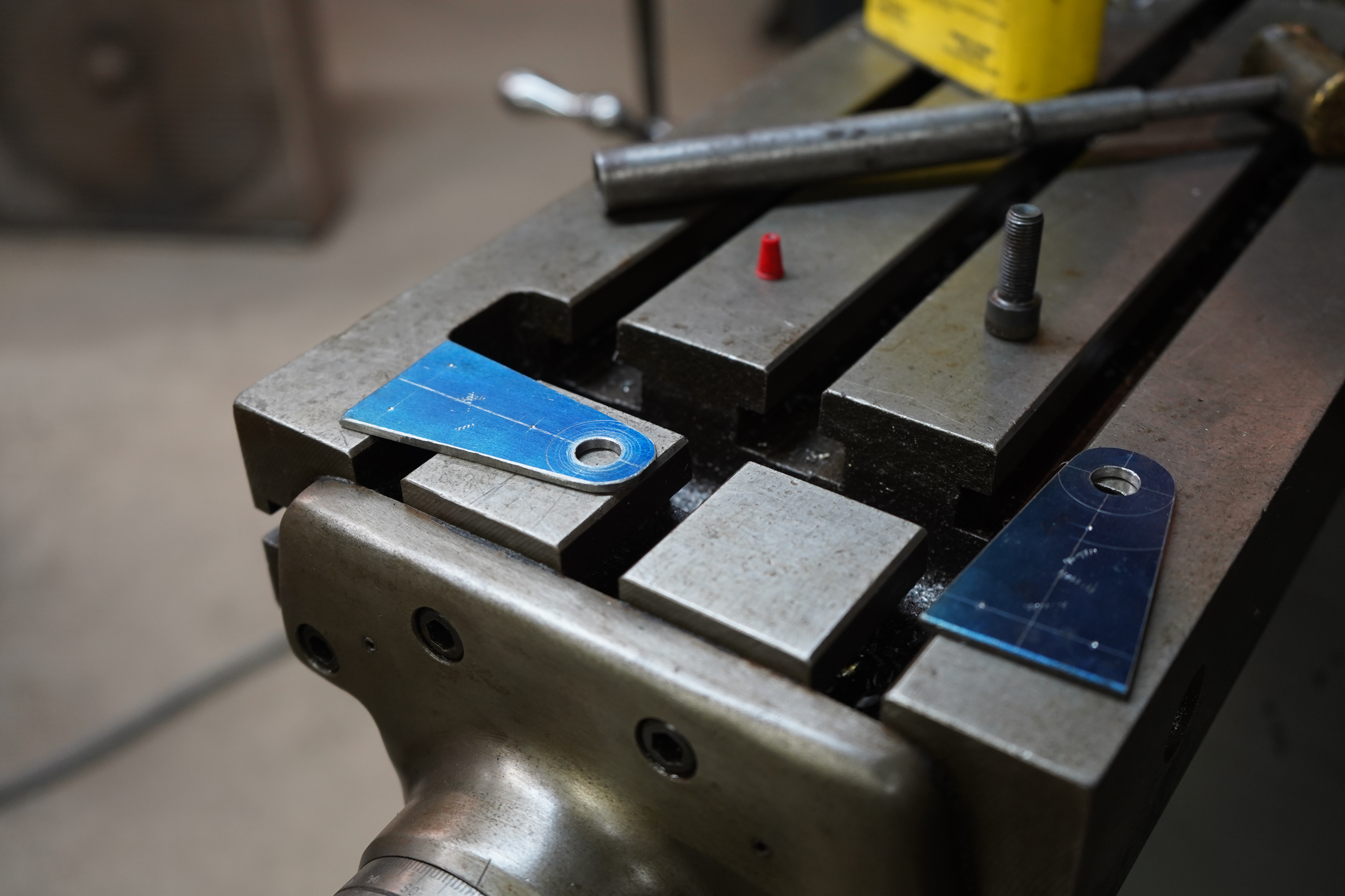
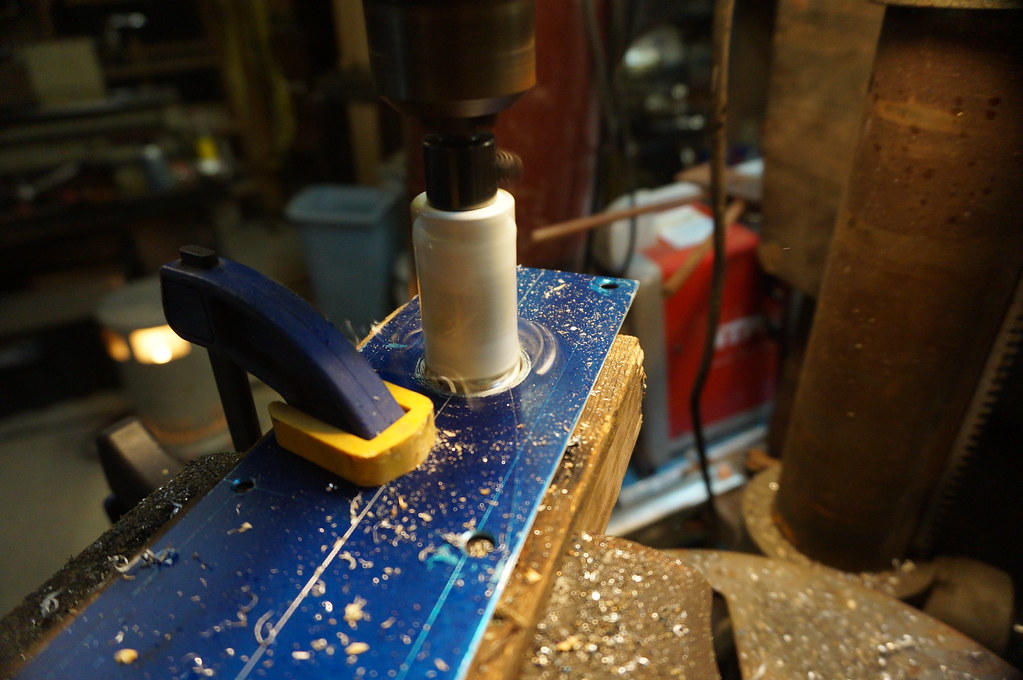
    Drilling out the center


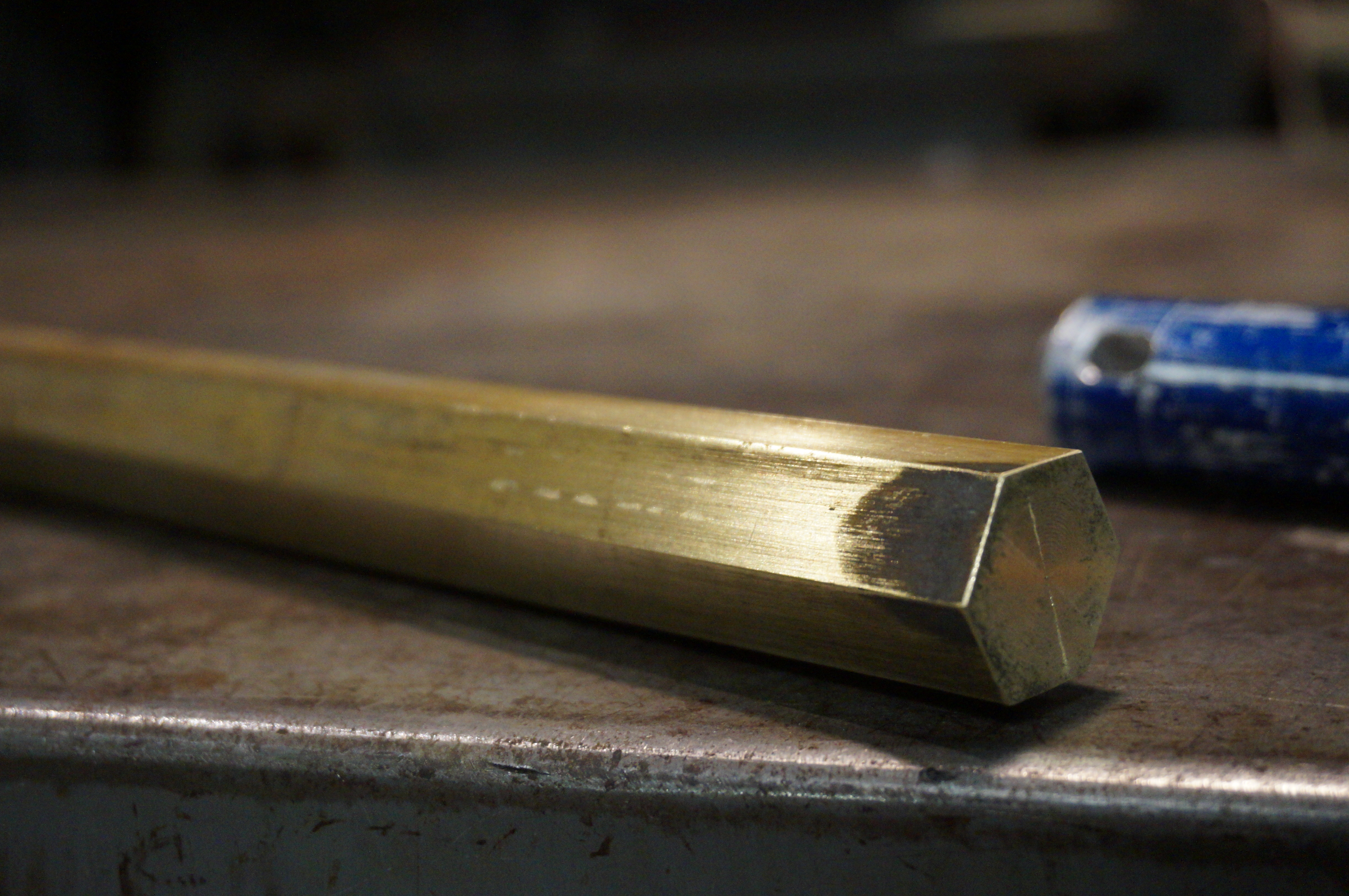
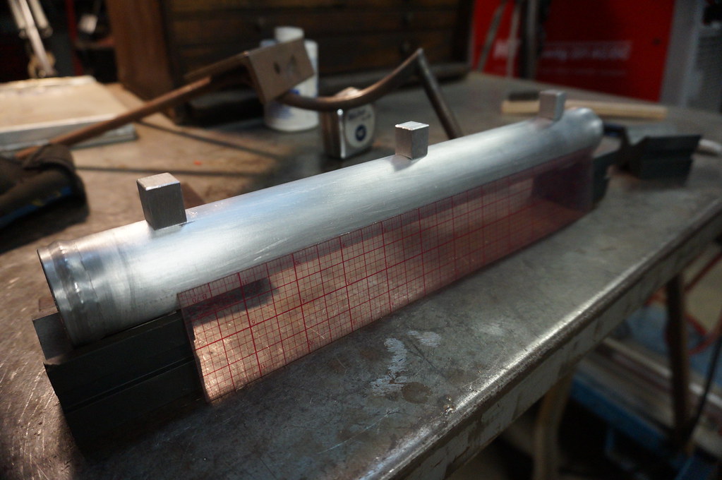
    Brass for great contrast


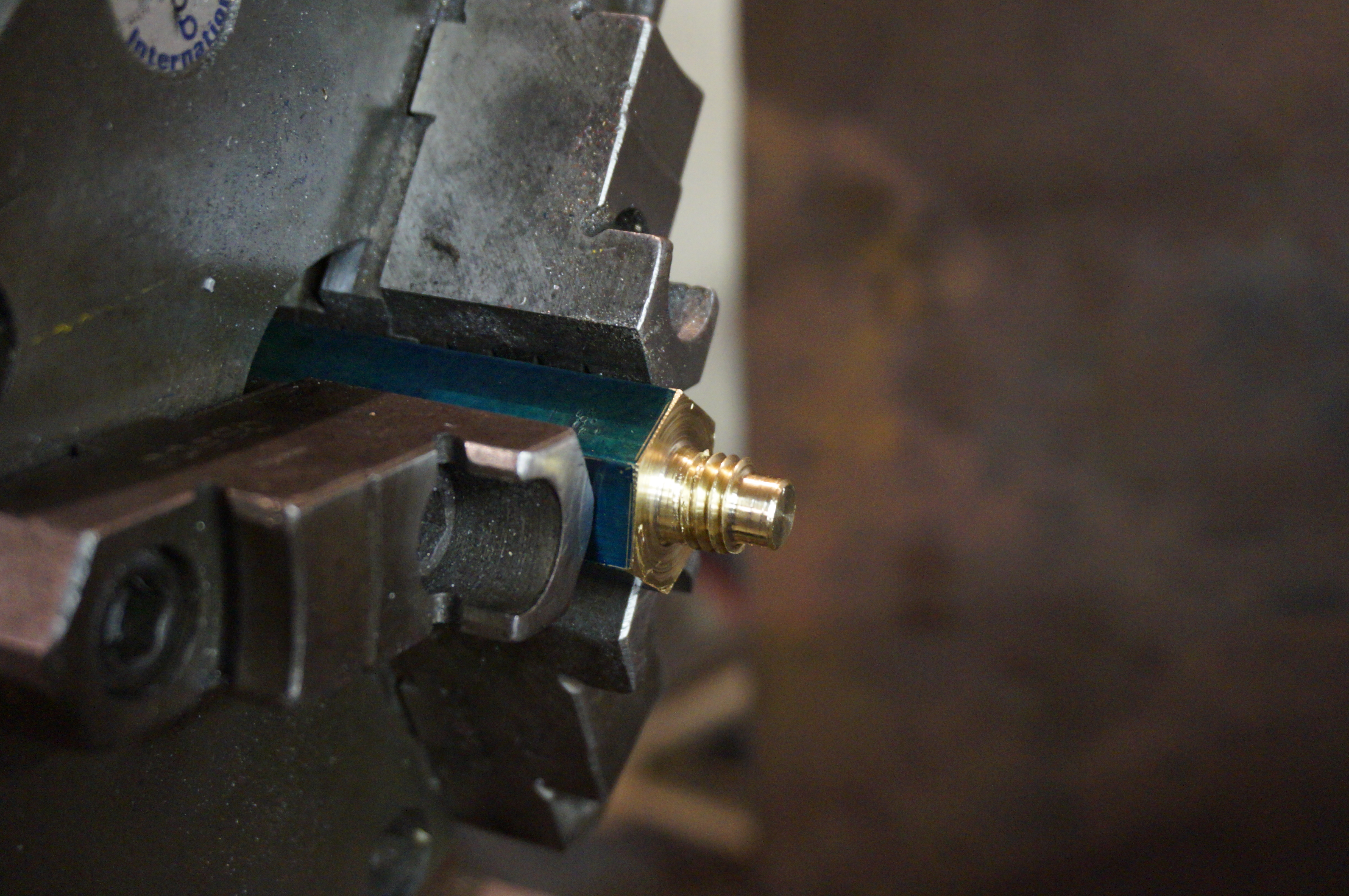
    Threaded the brass Hex


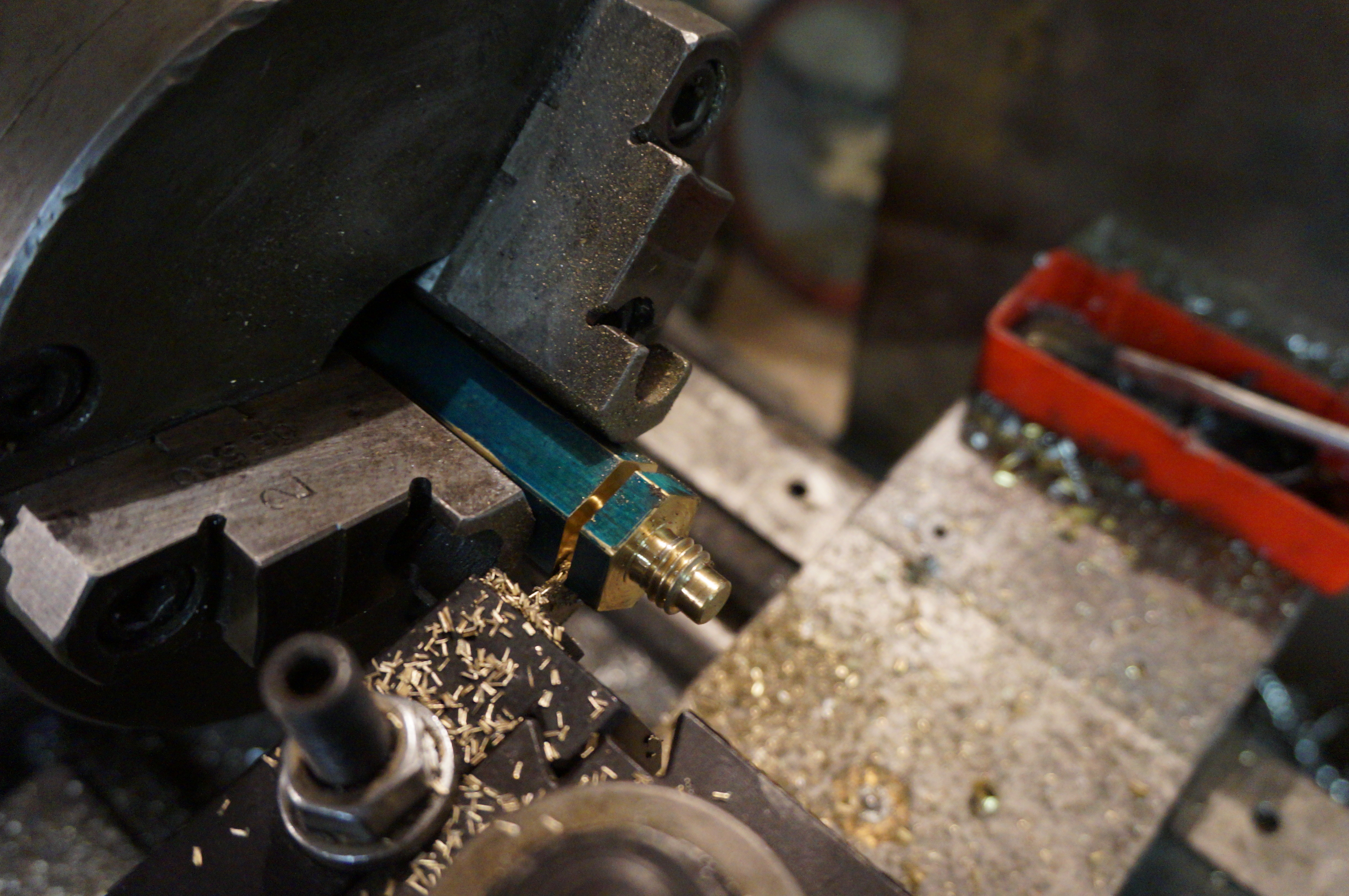
    Made a nice little clamp


    So everything you have just looked at forget it ever happened. I decided to ditch the whole brass clamp (I am sure I will find a use for it later)


    The new plan is to make more traditional type hood pins


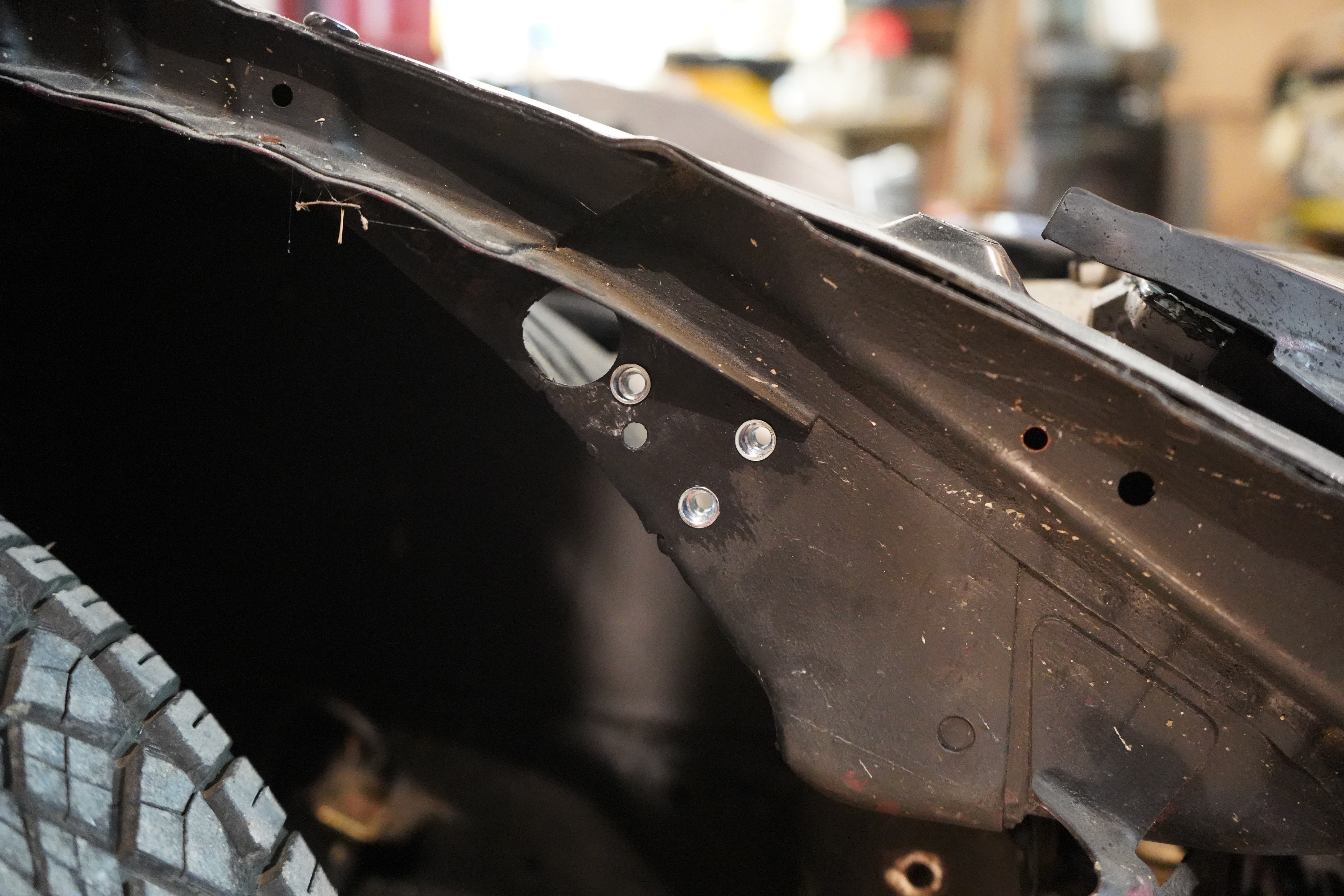
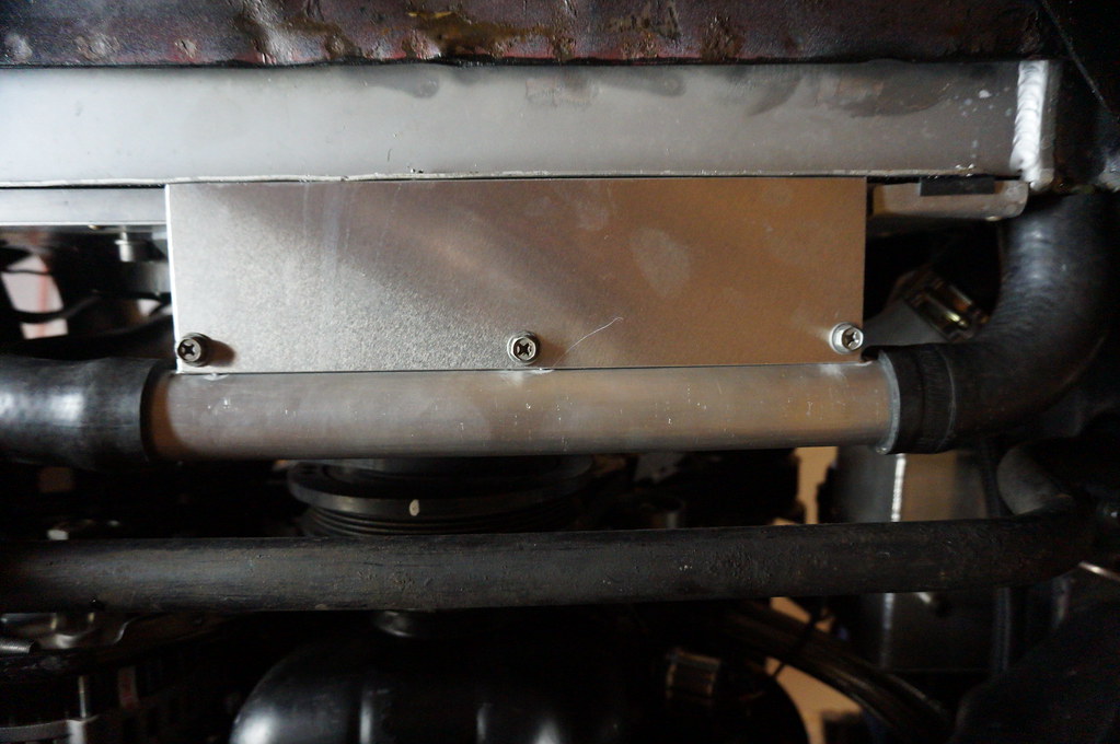
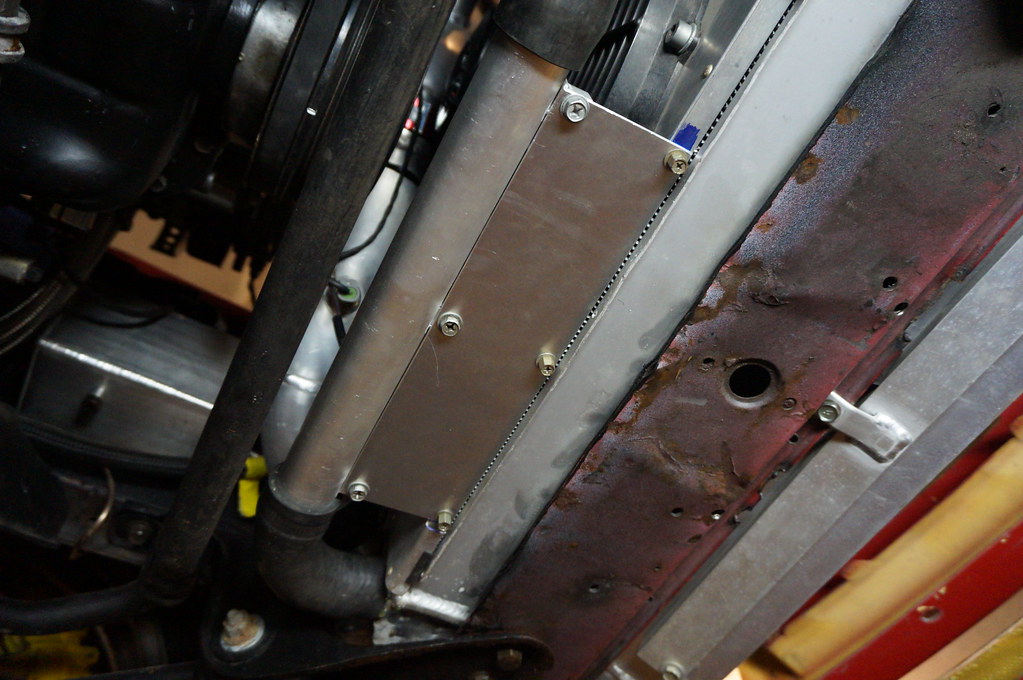
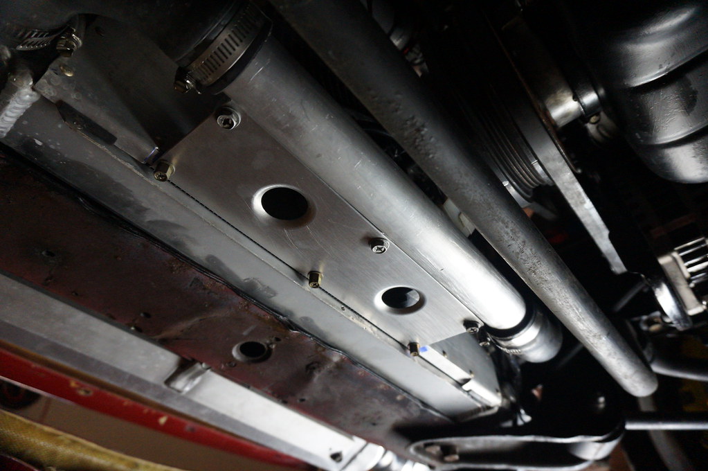
    Using these little holes on the inner fender for a mounting point


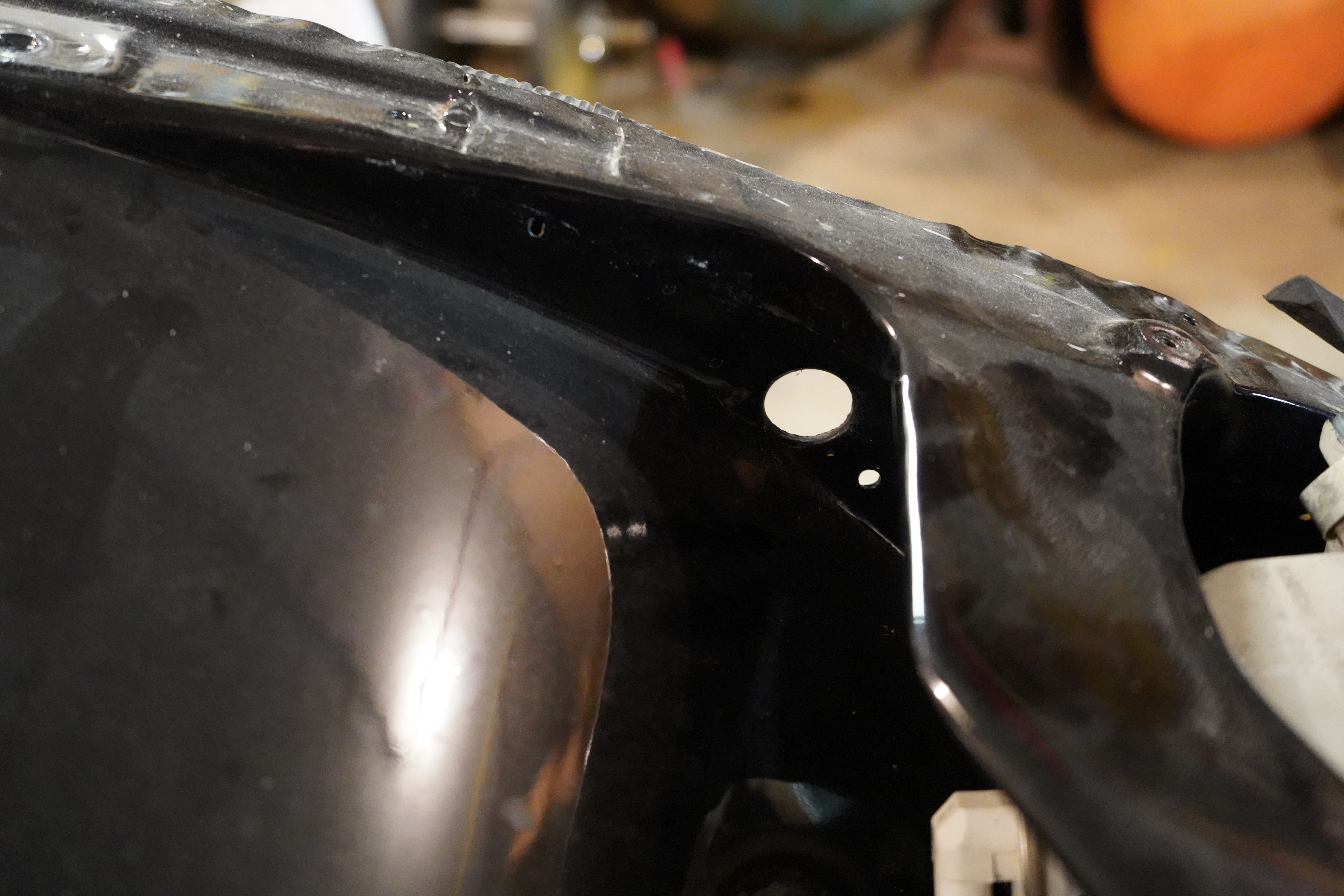
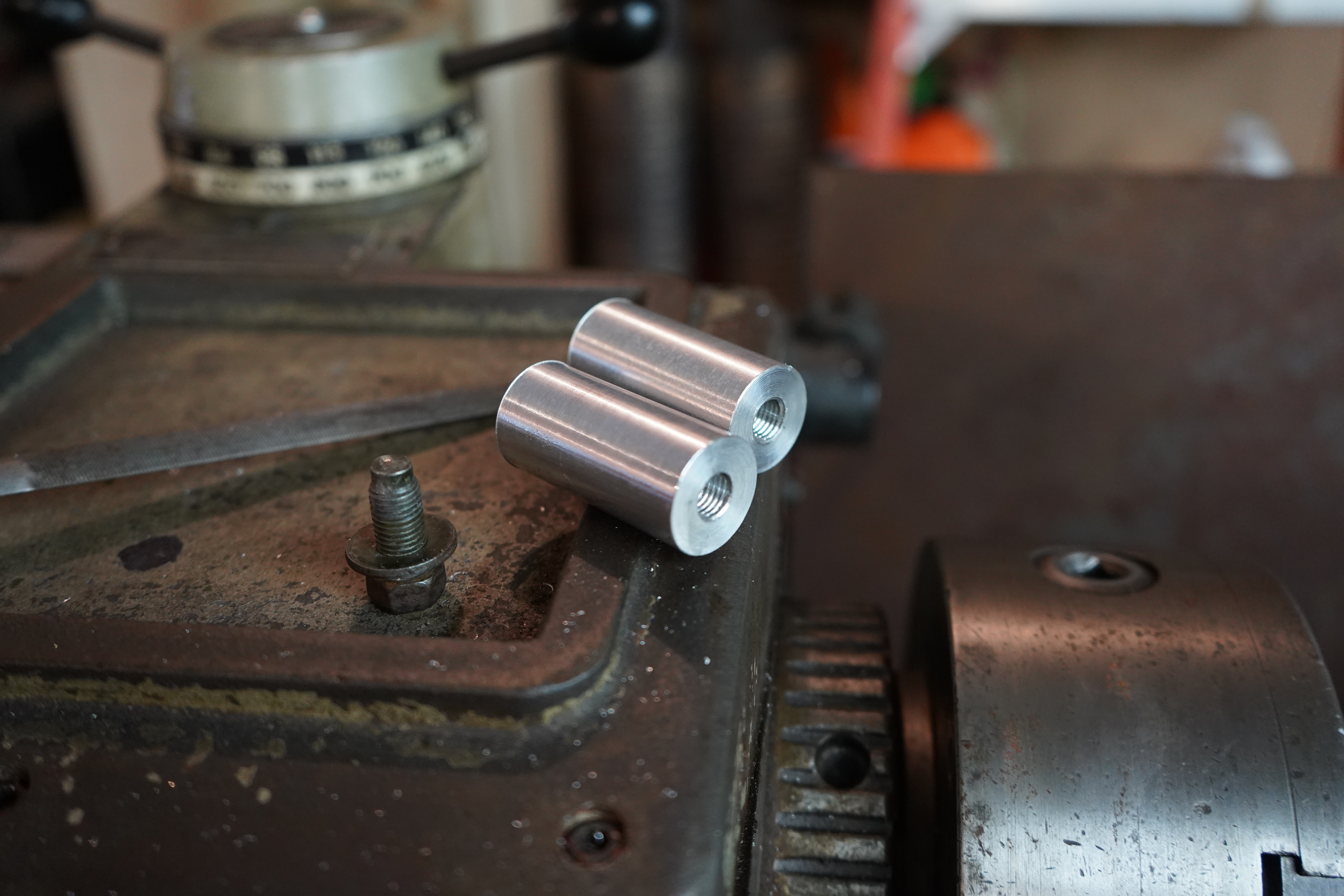
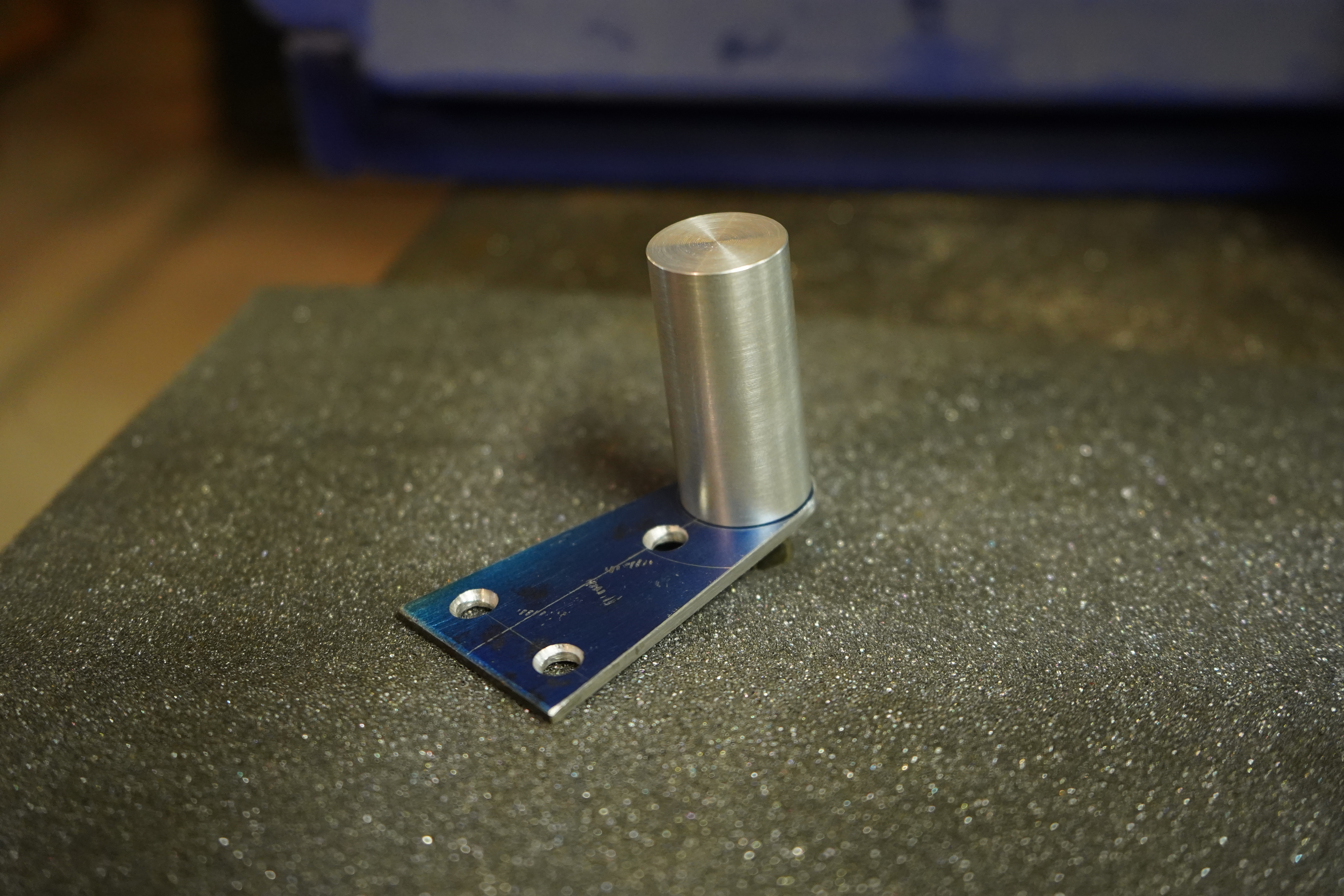
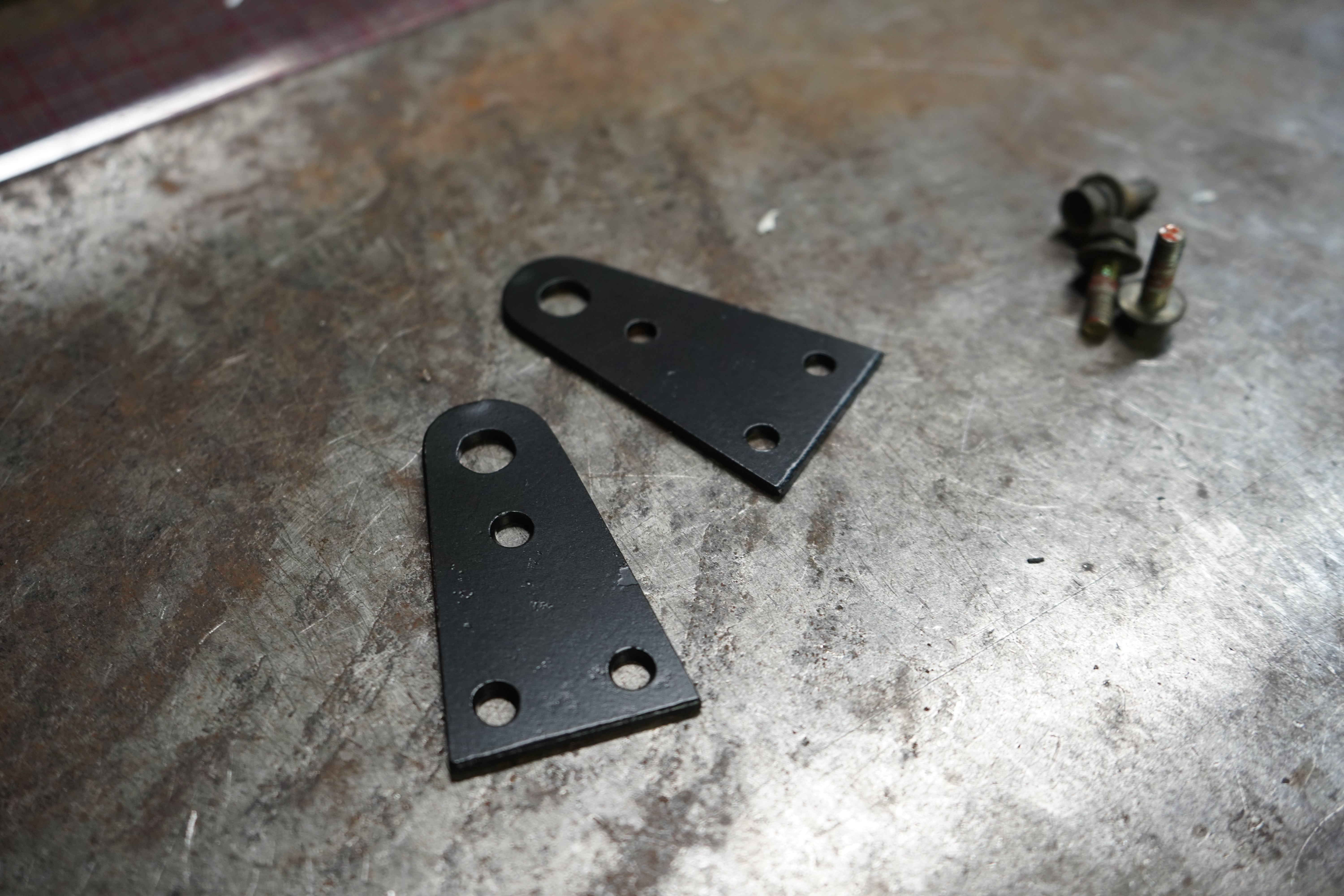
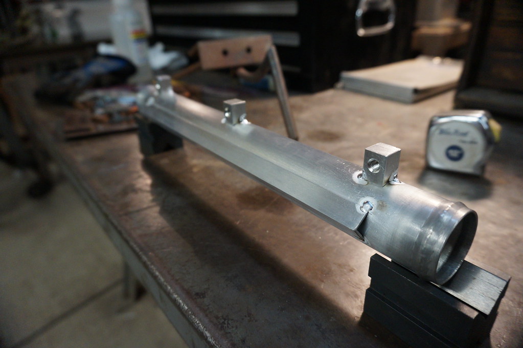
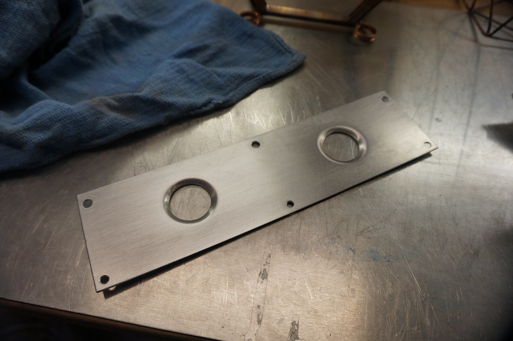
    Need to make a couple backing plates to mount the pins to


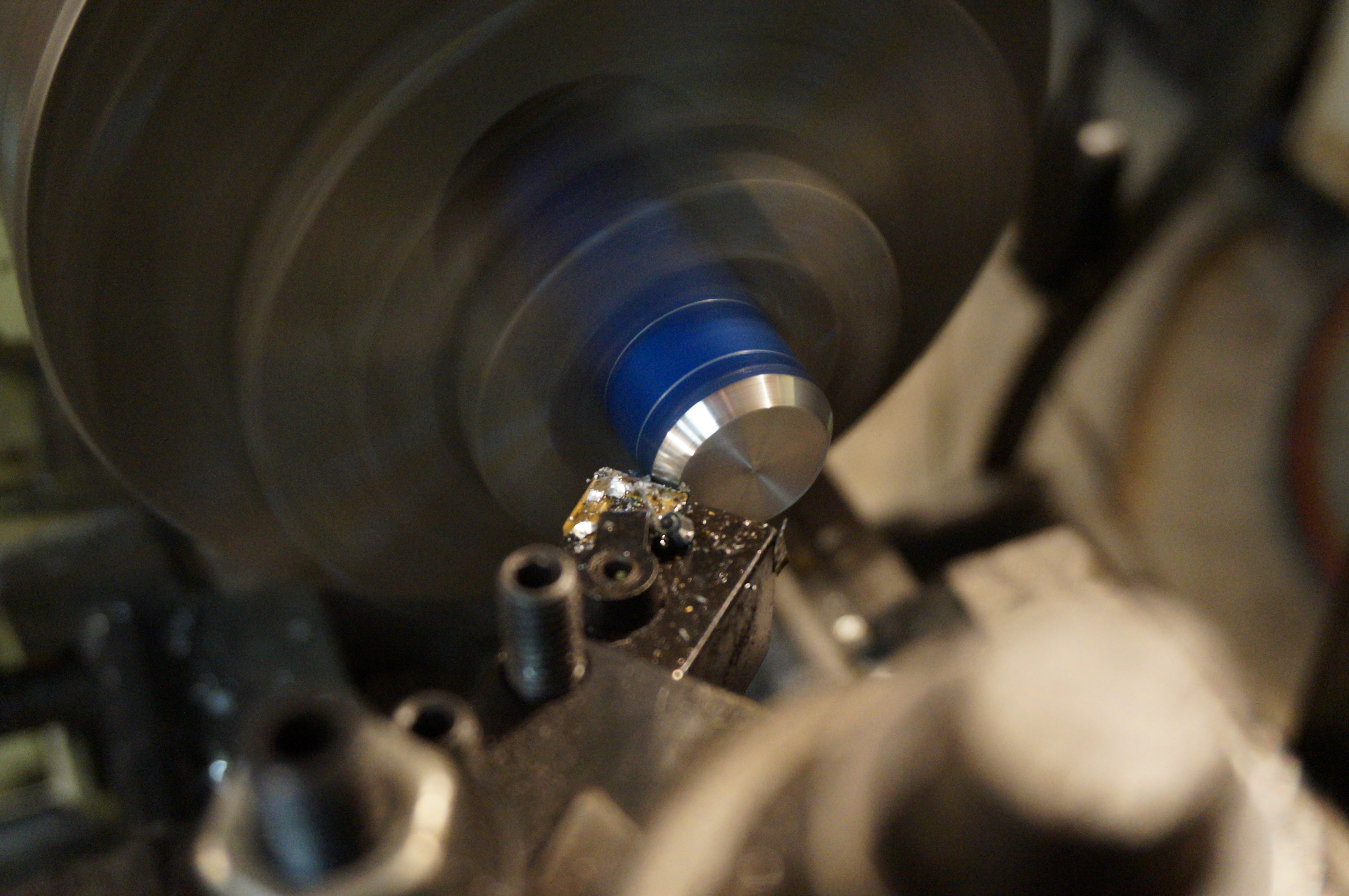
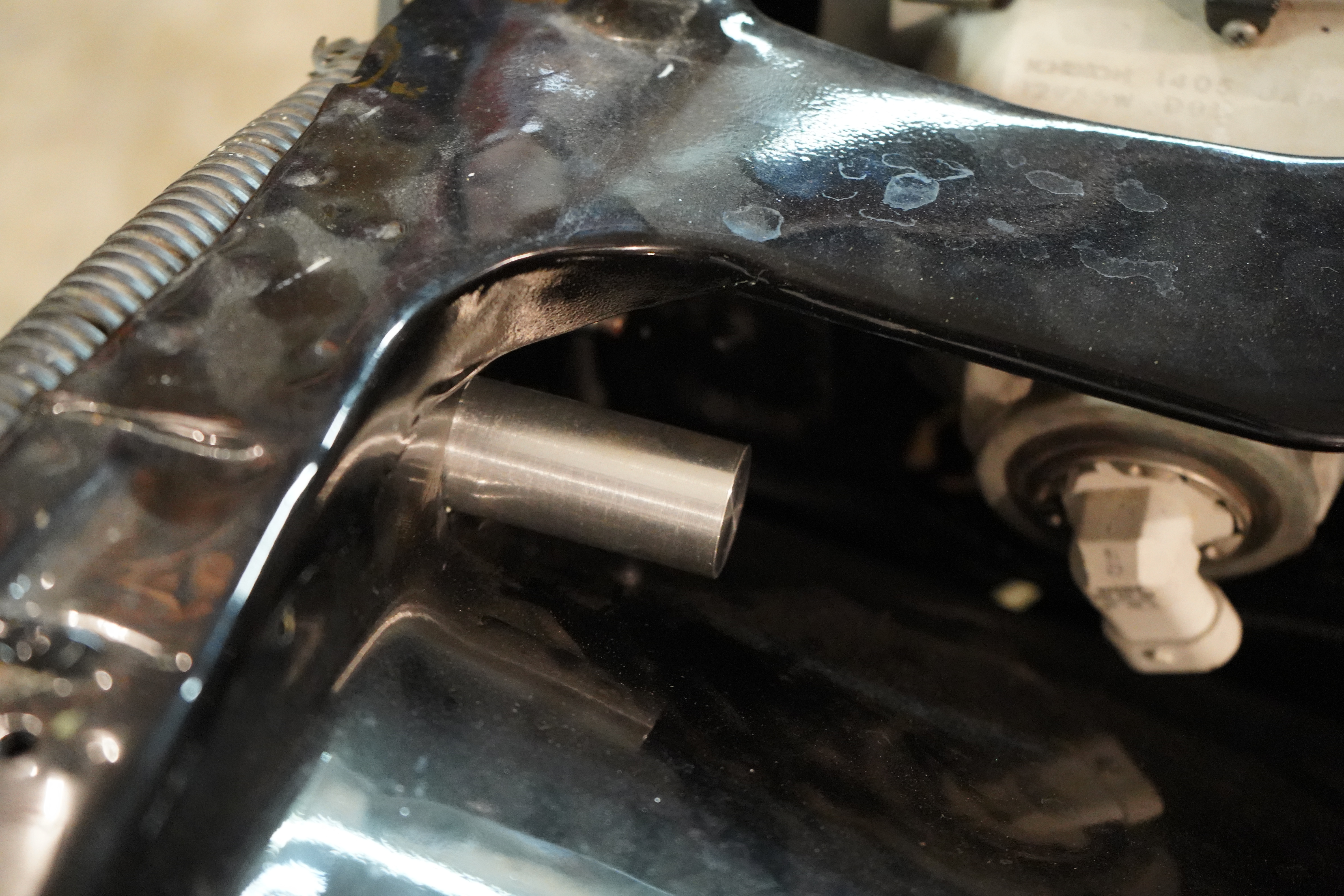
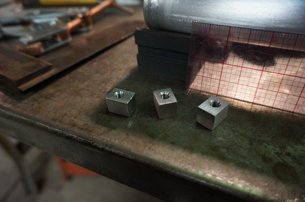
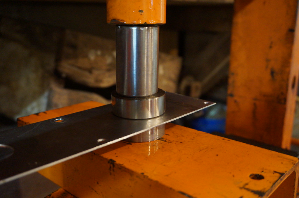
    These aluminum bosses are going to be what sets the height of the pins


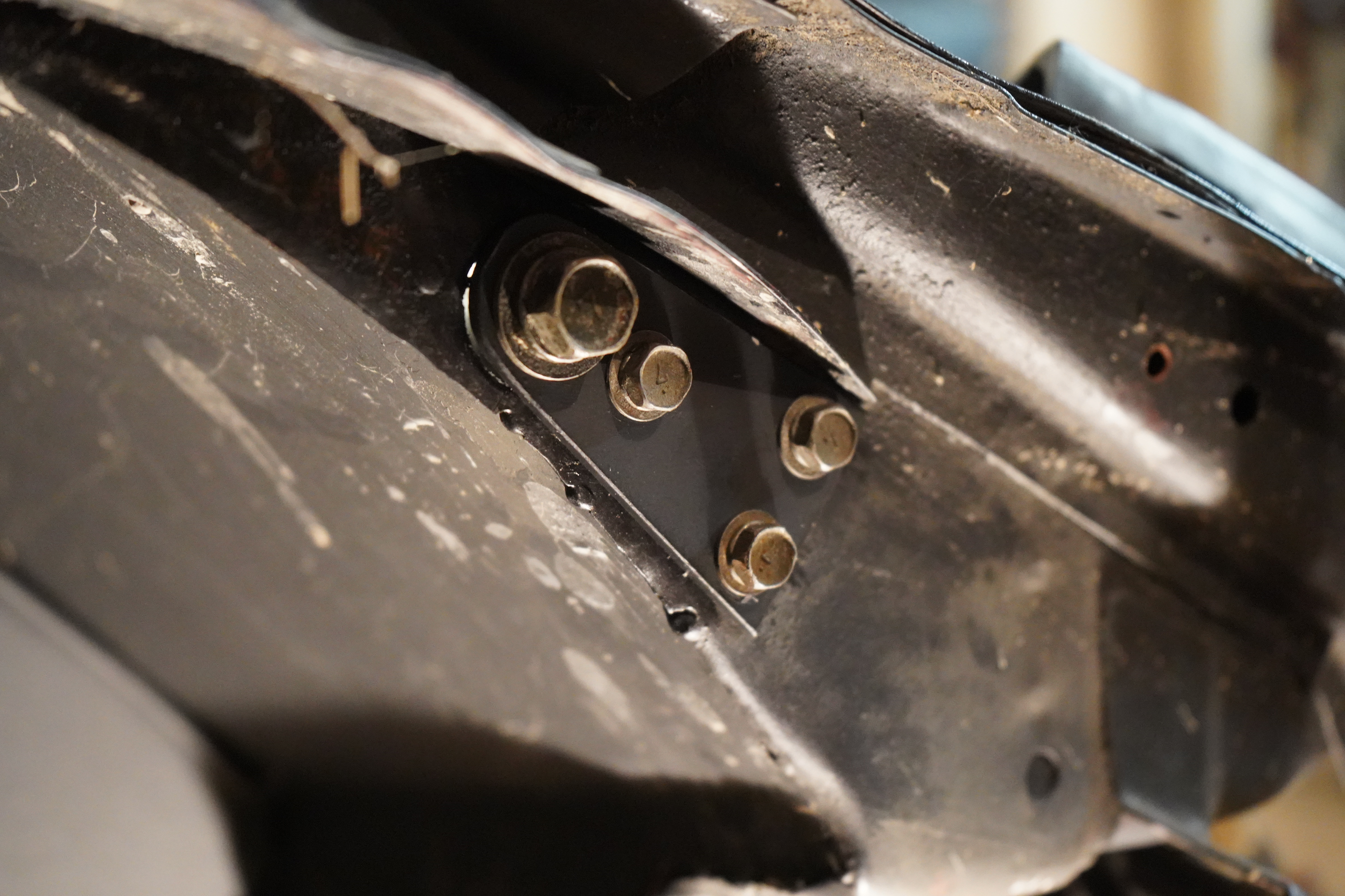
    Using some more threaded inserts to mount the backing plate to the inner fender


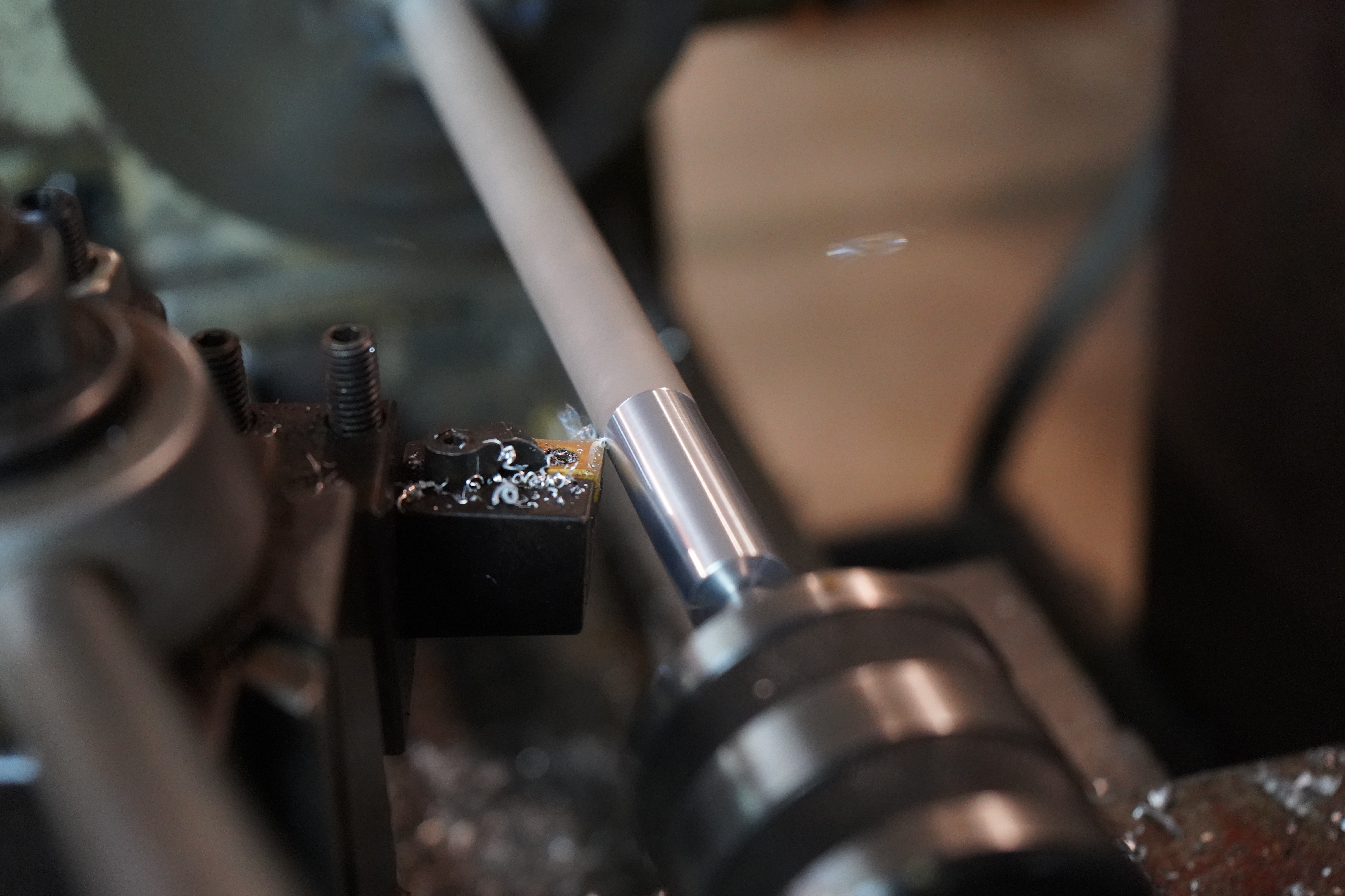
    The aluminum bosses will now be in position to attach the hood pins


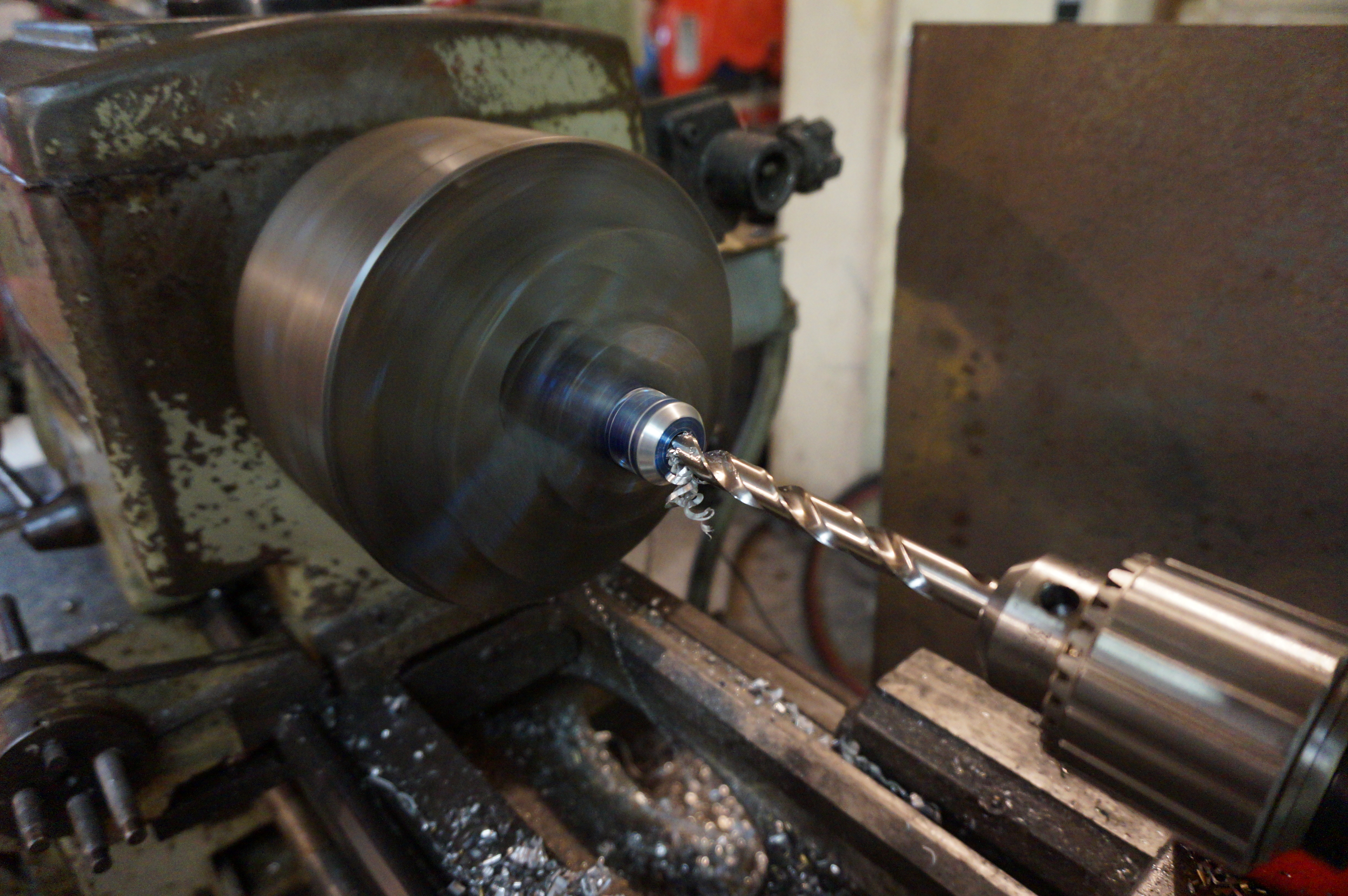
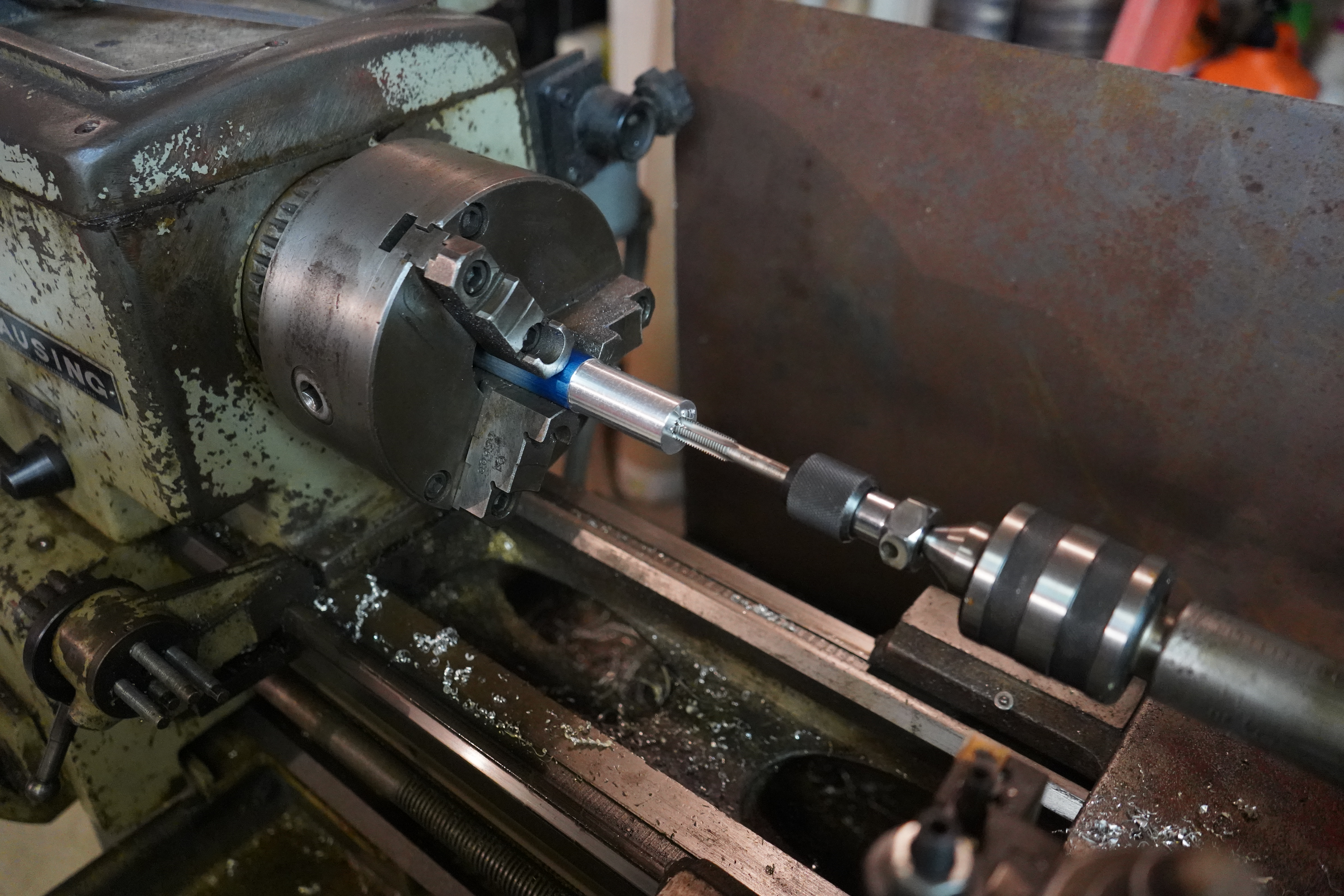
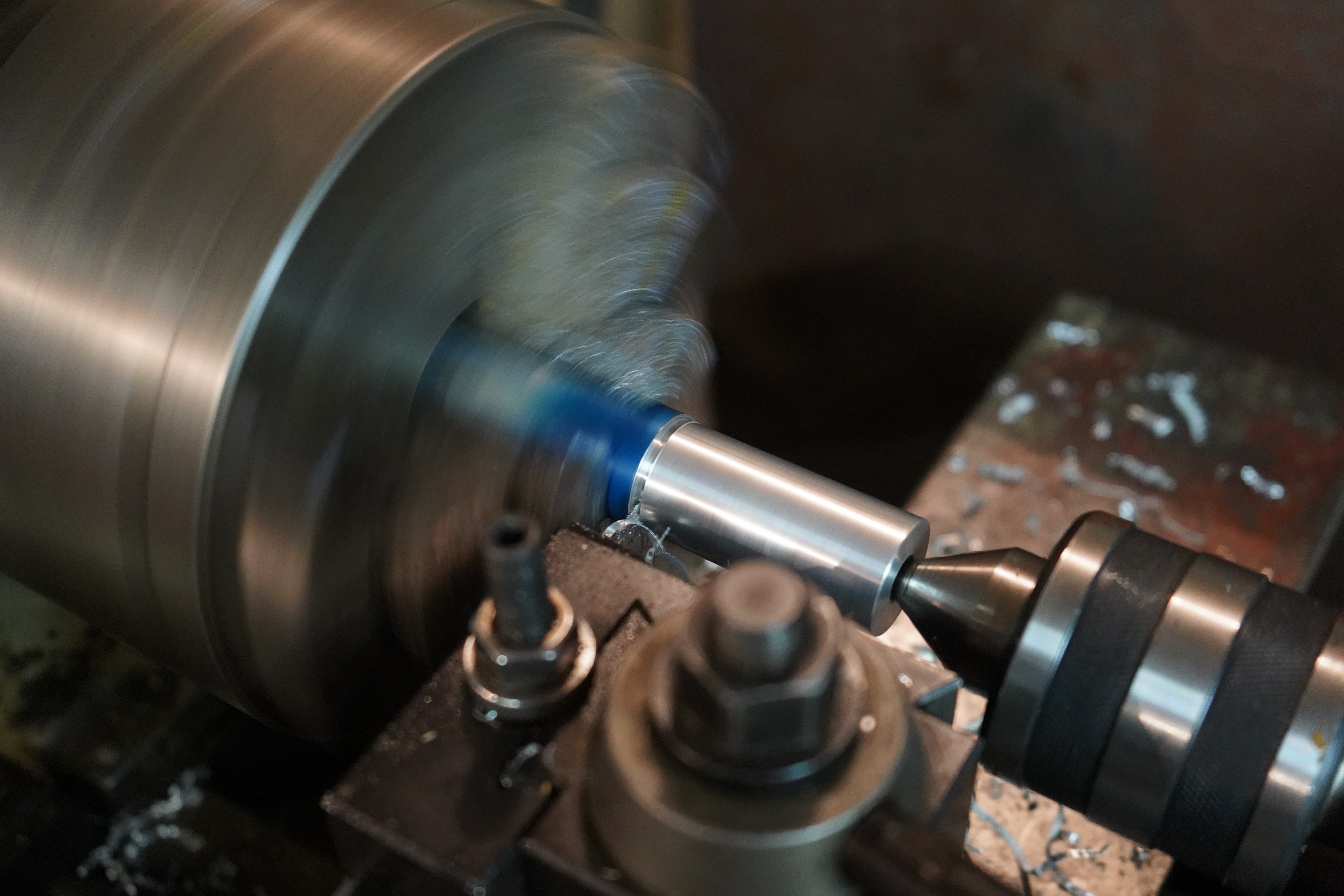
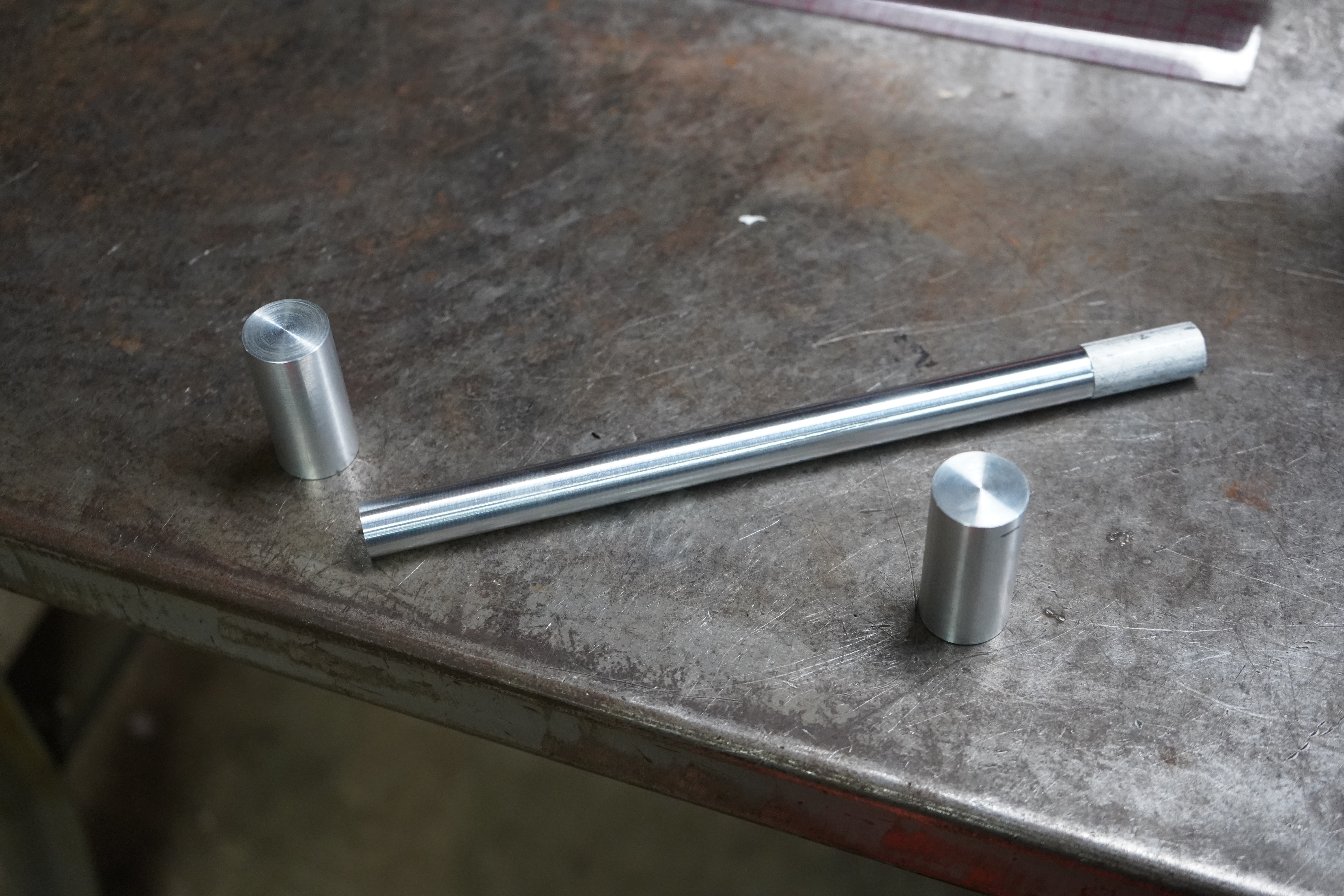
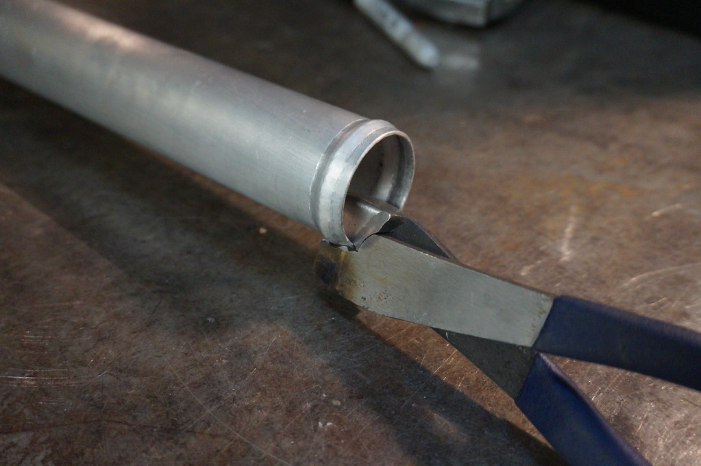
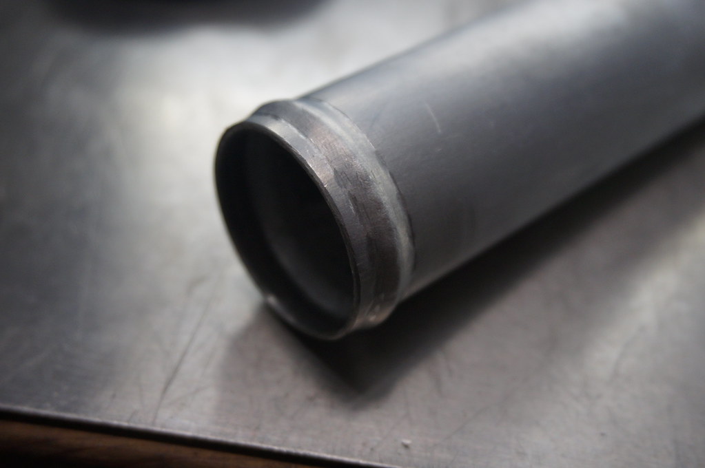
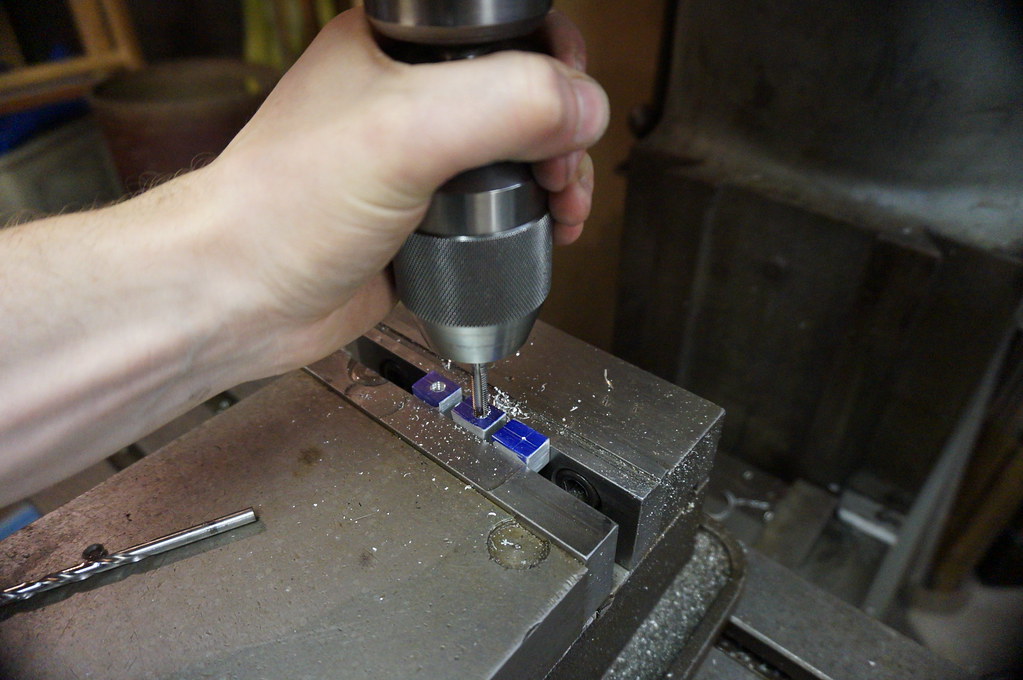
    Cutting the pins to diameter


    That is all I got for now!

    Leave a comment:


  • Tate
    replied
    I was about to get so salty if this thread was bumped without a post from OP. Still love your attention to detail man.

    Leave a comment:


  • nsogiba
    replied
    It just clicked that you are the same person that is building this Z as well as the M5 in the other thread. I frequently visit your threads and enjoy the attention to detail. Keep it up!

    Leave a comment:


  • EasySpeed*Inc
    replied
    Firstly I am going to say I have not touched the Z in a hell of a long time

    DSC00969 by tom maloy, on Flickr

    I have many things I still want to do to this

    DSC01005 by tom maloy, on Flickr

    It does run currently, so that's a plus

    DSC00963 by tom maloy, on Flickr

    DSC00023 by tom maloy, on Flickr

    Its not much but I decided to post some photos of the little bastard from over the last few months

    DSC01064 by tom maloy, on Flickr

    I have been busy with my other project, and this has been put on the back burner

    DSC00980 by tom maloy, on Flickr

    My M5 needed "maintenance", this has taken a bit longer than expected (I have started another build on here and I think you would enjoy it, http://www.stanceworks.com/forums/sh...M5-revitalized)

    DSC00985 by tom maloy, on Flickr

    That is a wrap for now, hopefully soon I can get back to the Z and do the rest of the cool stuff

    DSC08543 by tom maloy, on Flickr

    Leave a comment:


  • slamitall
    replied
    What happened to this thread? Just read the whole thing and want MOAR

    Leave a comment:


  • alantw-15
    replied
    Originally posted by MikeyRa View Post
    Dude, holy shit! I just read the entire thread and I absolutely applaud you!

    My only qualm is with the soldering on the wire harness. Soldering does not belong on a vehicle. Some may call me out for nitpicking but it could potentially lead to more issues that require a lot of time and digging to rectify.

    Quoting myself here from another thread:

    This is great and correct advice which I concur.
    I work on large mining machines. Often under spec'ed wires fracture. Then they are soldered repaired. The solder, without exception, will again fracture in surprisingly short time. This failure manifests as bizarre and misleading electrical faults. We now don't solder anymore. We use straight crimps with heat shrink properties to seal it up after.


    Also waiting for updates on this amazing build...

    Leave a comment:


  • ItsaCorolla
    replied
    updates?
    Last edited by ItsaCorolla; 06-14-2018, 04:40 AM.

    Leave a comment:


  • MikeyRa
    replied
    Originally posted by proboner View Post
    ... but it just seems so over the top excessive.
    That's not a bad thing. If the car was built to handle 300whp and you used it at 300whp then you would be maxing out the capabilities and abilities of the engine, chassis, safety, etc. If the car was built to handle 600whp and used only at 300whp then you have a margin for safety and potential for future work. My numbers are purely for example but it helps show the concept.

    I'd much rather over build and be at 60-80% duty cycle on parts and chassis then be pushing 100% and straining everything all the time.

    Leave a comment:


  • proboner
    replied
    The craftsmanship and engineering and tools are just amazing... but it just seems so over the top excessive.

    Leave a comment:


  • MikeyRa
    replied
    Dude, holy shit! I just read the entire thread and I absolutely applaud you!

    My only qualm is with the soldering on the wire harness. Soldering does not belong on a vehicle. Some may call me out for nitpicking but it could potentially lead to more issues that require a lot of time and digging to rectify.

    Quoting myself here from another thread:

    One word of recommendation though, solder does not belong in a car. Proper crimp and splice connections will out live and out perform solder in a vehicle. Use proper adhesive lined heat shrink butt crimps with a good crimping tool. Always give the wires the tug test before shrinking down the connectors. If it fails the tug test, then the connection must be redone. A proper crimp is stronger than the wire its self.

    Only place solder should be used is in PCB boards. Wires should be crimp only.

    The rigidity of a solder connection can fail and crack due to vibrations and heat cycles.

    Leave a comment:


  • DUTCHswift
    replied
    I love updates on this build.

    Leave a comment:


  • Benwalsh91
    replied
    Just read from start to finish.

    this is absolutely amazing! keep up the good work.

    Leave a comment:


  • Asshole Bicycle
    replied
    So much work for something most people will never see. I love it.

    Leave a comment:


  • EasySpeed*Inc
    replied
    Now that is a radiator hose!

    DSC04089 by tom maloy, on Flickr

    Whoops
    DSC04105 2 by tom maloy, on Flickr

    The idea here is to add a hard ridged section on the lower radiator hose
    DSC04092 by tom maloy, on Flickr


    Hmmm something missing??
    DSC04116 by tom maloy, on Flickr

    Ah! much better
    DSC04130 by tom maloy, on Flickr

    Home made bead roller
    DSC04148 by tom maloy, on Flickr


    DSC04142 by tom maloy, on Flickr

    So fancy, (it's just a cut down electrical crimper)
    DSC04152 by tom maloy, on Flickr


    DSC04167 by tom maloy, on Flickr


    DSC04179 by tom maloy, on Flickr


    DSC04184 by tom maloy, on Flickr

    Mounting lugs
    DSC04216 by tom maloy, on Flickr

    Drilled and tapped
    DSC04243 by tom maloy, on Flickr


    DSC04259 by tom maloy, on Flickr


    DSC04273 by tom maloy, on Flickr


    Adding a bit of rigidity as the tube itself is apart of the mounting system
    DSC04160 by tom maloy, on Flickr


    DSC04204 by tom maloy, on Flickr

    If you need a steady rest for welding try getting yourself a multi position magnetic base, works flawlessly
    DSC04336 by tom maloy, on Flickr


    DSC04358 by tom maloy, on Flickr


    DSC04268 by tom maloy, on Flickr

    Mounting plate
    DSC04286 by tom maloy, on Flickr


    DSC04291 by tom maloy, on Flickr

    Fastens to the hard rad pipe and will mount to the radiator fan shroud
    DSC04361 by tom maloy, on Flickr


    DSC04405 by tom maloy, on Flickr


    DSC04394 by tom maloy, on Flickr


    DSC04422 by tom maloy, on Flickr

    Not quite done yet
    DSC04424 by tom maloy, on Flickr


    DSC04431 by tom maloy, on Flickr

    I am about that dimple life
    DSC04438 by tom maloy, on Flickr


    DSC04441 by tom maloy, on Flickr

    Now its done
    DSC04456 by tom maloy, on Flickr

    Leave a comment:


  • Fons
    replied
    Woah al the fabrication porn on this car is truly amazing. The quality of your work is top notch, keep it coming.

    Leave a comment:

Working...
X