Announcement

Collapse
No announcement yet.

Fiona: A 1975 2002

Collapse
X
 
  • Filter
  • Time
  • Show
Clear All
new posts

  • #46
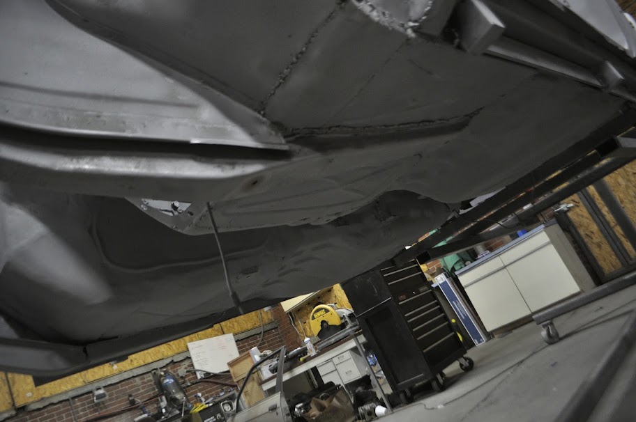
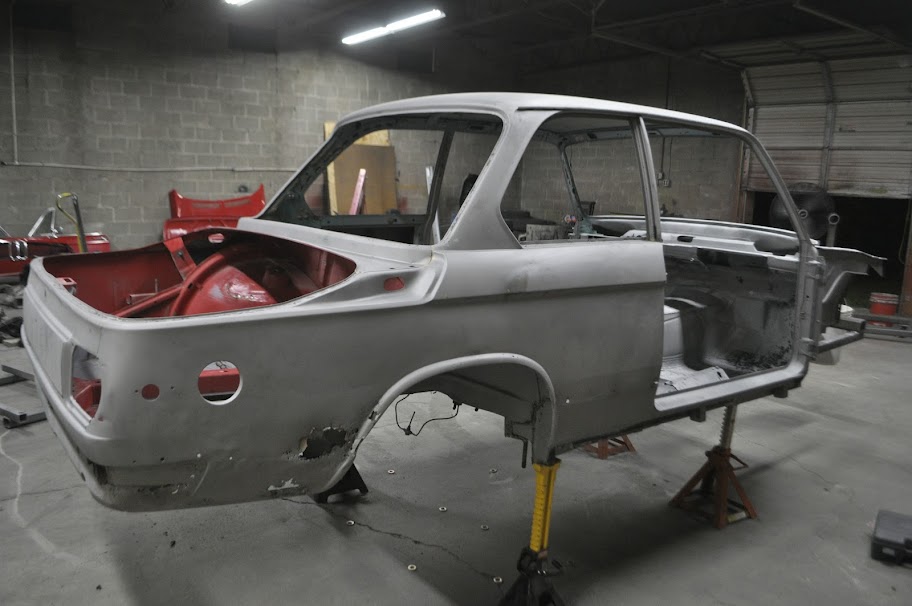
    The rest of my time has been spend stripping the car down to bare metal. After finishing all of the exterior surfaces, I started working on the underbody. The sand blasting process worked great for the surfaces with just paint and bondo (in some cases LOTS of bondo lol), but it was pretty much useless on anything with rubberized undercoating. Which is the entire underside of the car. Because of this, I had to bust out the 4" grinder with the wire wheel attached and strip off all the rubbery material. This leaves the base metal primer, which I'll sandblast off as a final step.


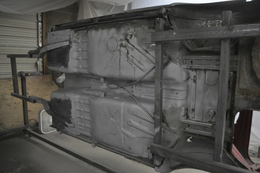
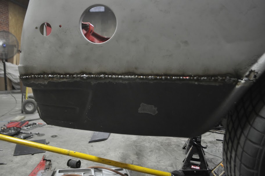
    Here's a pic of the underbody after stripping off the rubbery undercoat. It's kinda hard to see, but the grey/greenish area's are the base metal primer ready to be sandblasted. The lighter grey area is already sandblasted metal, and the black is an aftermarket undercoating from my previous repairs. It will also be coming off to bare metal, but it needs to be ground off still.


    What does half a car worth of undercoating look like?? This, the pile is about half and inch thick.


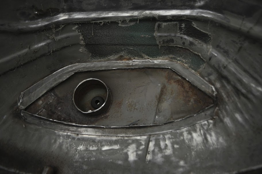
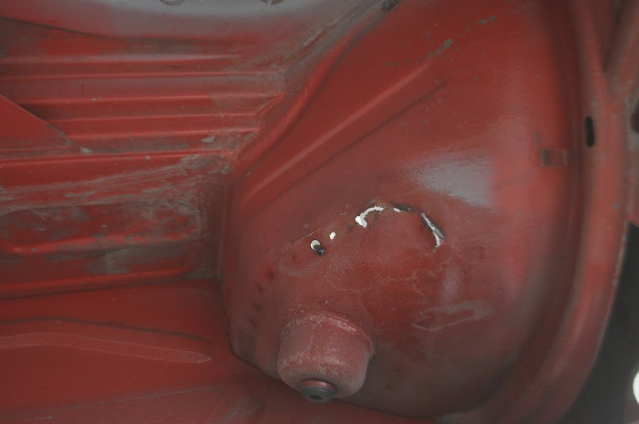
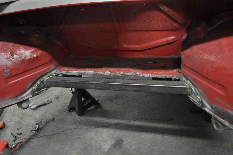
    After spending a few hours working on the bottom of the car, I turned my attention to the rear fender wells. The first picture is after I wire wheeled out all of the undercoating. This showed me what places were rusty and needed attention.


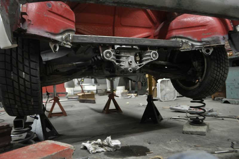
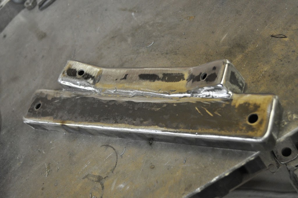
    For my rear suspension, I'm going to be running a true coilover that ties into the roll cage in the trunk area. This means that the stock spring perch and reinforcement are just taking up space, so out they come.


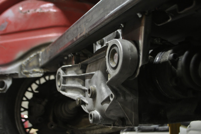
    With the inner section cut out, it just left the spot welded attachments which gave me a great chance to use my new spot weld cutters. Here you can see the individual spot welds on each piece.


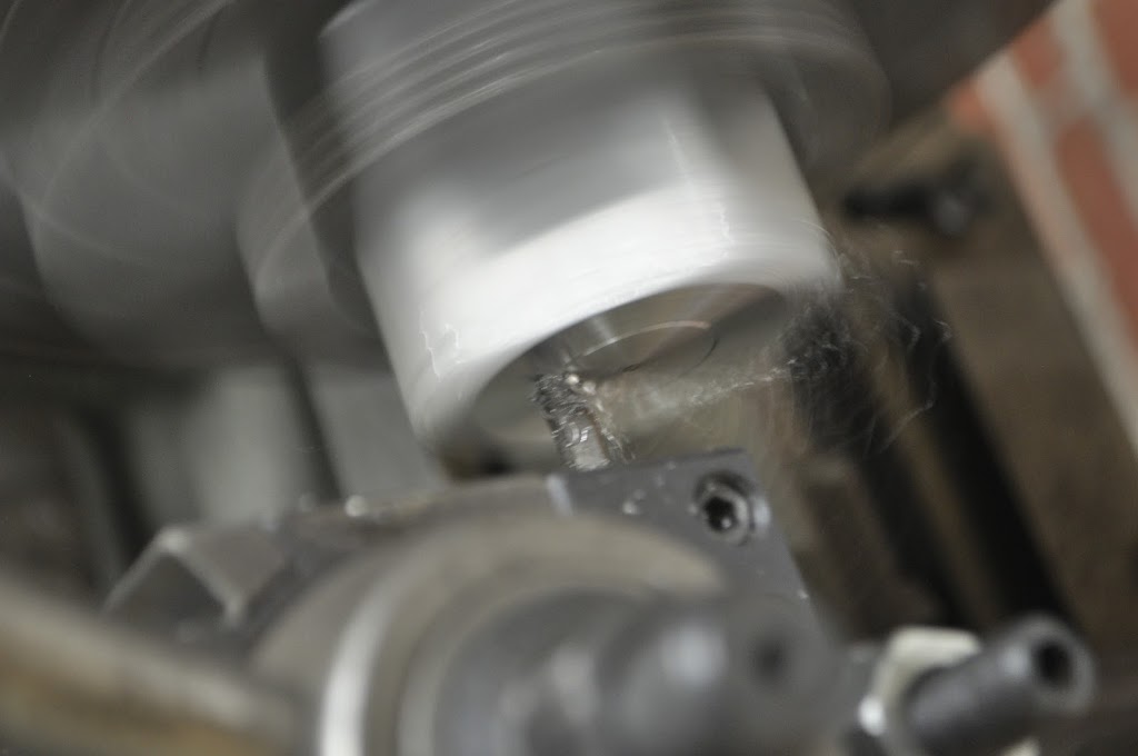
    First I punched the center of each spot weld so the cutter could locate properly.


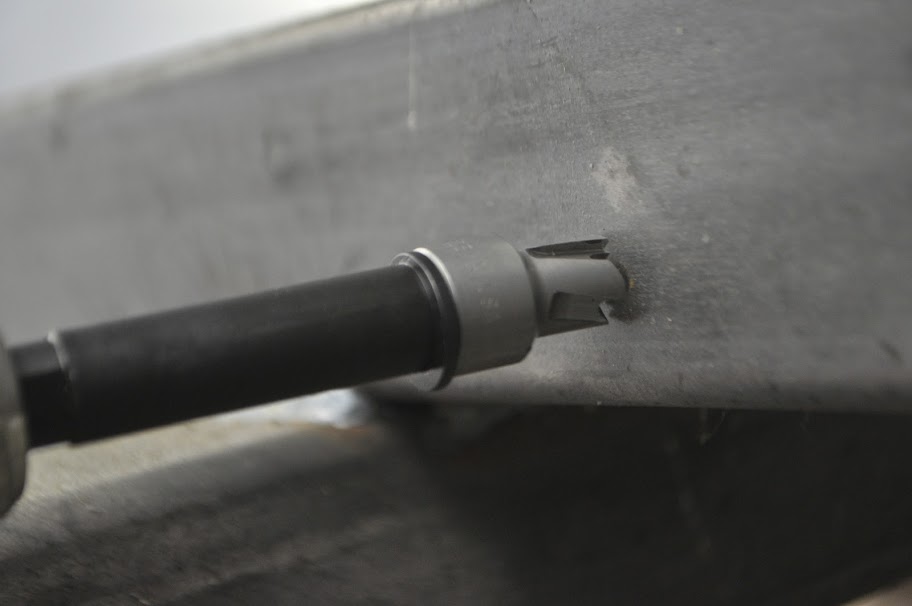
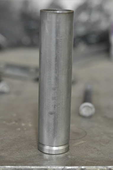
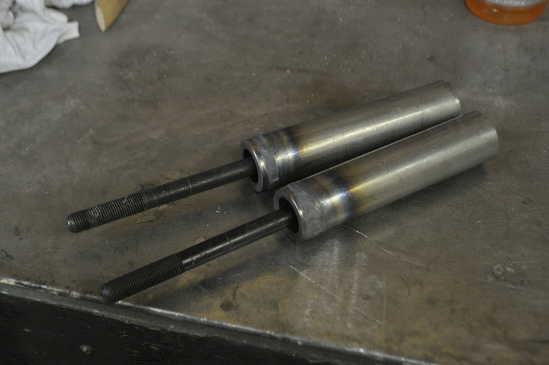
    And here you can see the cutter. The center rod is spring loaded, so it helps to locate the cutter without drilling into the second layer of metal.


    As you push the bit in, the rod retracts keeping the bit centered.


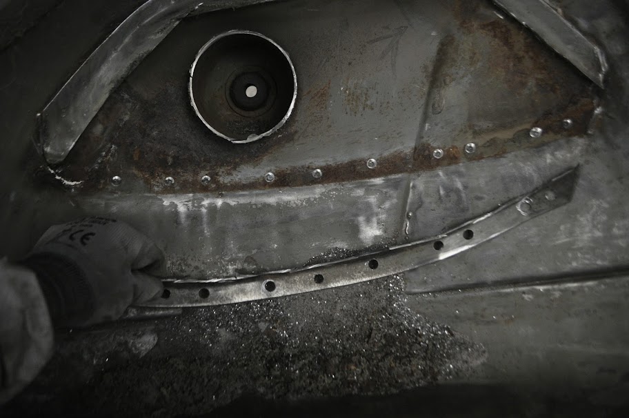
    Now all that was left was to drill out all the spot welds for the spring perch support.


    Bottom Side Done:


    Top side Done:


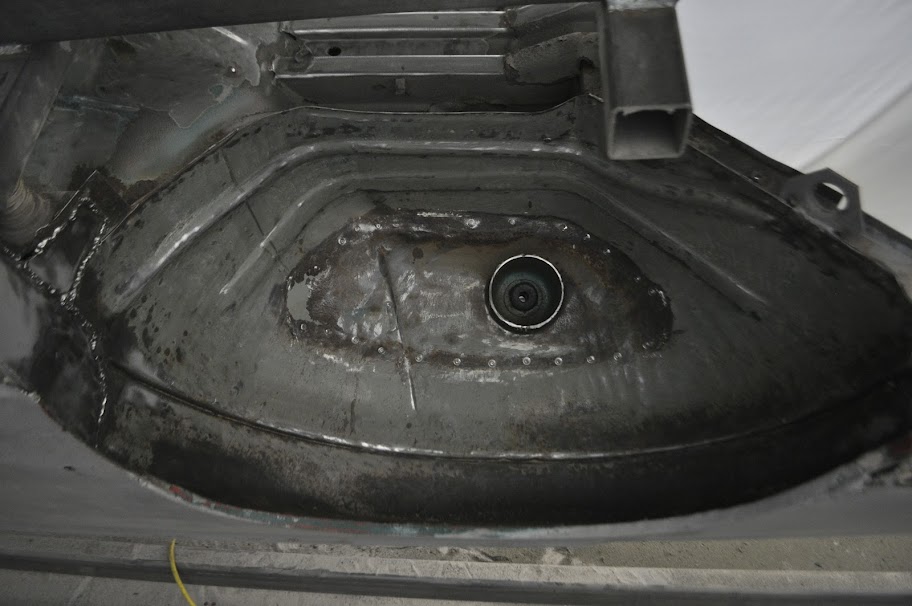
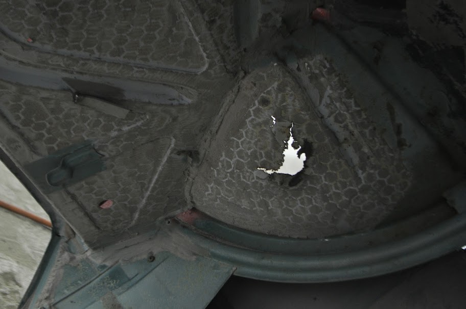
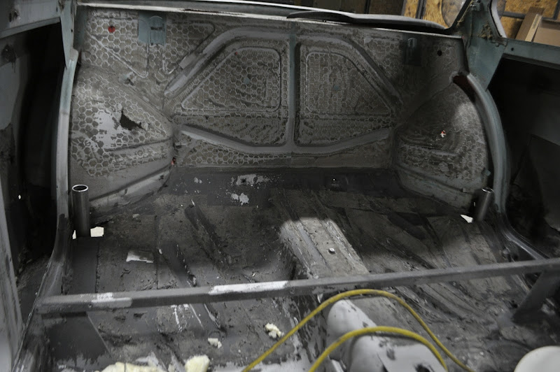
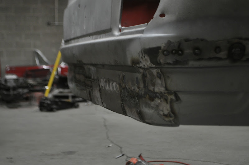
    After removing it, I'm really glad I did. You can see all the rust that was hiding underneath it. Luckily with the perch out of they way it will be very simple to patch it and tie it into the cage with my shock mount.


    The next steps are to remove the spring perch from the other side (passenger) and then sandblast the underbody for hopefully the last time. Then I just need to blast the interior, which shouldn't take much time at all thanks to the thin layer of paint, and the trunk.
    Tinker Engineering - 2014

    Mica - 2000 BMW 323i - The one that started it all
    Fiona - 1975 BMW 2002 - The Definition of Project Creep
    Heidi - 1988 BMW M5 - The piece of BMW history
    Silvia - 2013 Subaru WRX - Stock, for now

    Comment


    • #47
      More progress on the underbody today. First up was removing the spring perch on the passenger side.

      Hmm, I wonder what's under there:


      Surprise!! More Rust!


      Wheel Well after drilling out the spot welds and grinding off all of the undercoating. Now it's ready for sand blasting:


      The worst of the rust was actually on the passenger compartment side this time. Either way, it'll get cutout and replaced.


      And to think one of the reasons I bought this car was because it had solid shock towers. :


      How it looks from the passenger compartment. Think of it as ventilation for the rear seat passengers.


      Here's the underbody after getting blasted. Pleasantly surprised with how solid the metal is here, both the original metal and my patches from two years ago are holding up well.


      I think there may have been a hoard of angry chickens in my car at one point in time.


      And finally here's the same wheel well after being blasted. Fairly clean, just needs the one patch and some modification for my true-coilover setup.


      Last but not least, I picked up a GoPro Hero2 this past week. I got it mostly for recording drives and other outdoor activities (snowboarding, hiking etc), but until then I'm also going to use it to help document the build in a different way than just the pictures. That being said I don't really want to take it in the booth while I'm sandblasting, so that will have to wait until I'm done with this stage. Hopefully here soon.


      Thanks for Looking!
      Tinker Engineering - 2014

      Mica - 2000 BMW 323i - The one that started it all
      Fiona - 1975 BMW 2002 - The Definition of Project Creep
      Heidi - 1988 BMW M5 - The piece of BMW history
      Silvia - 2013 Subaru WRX - Stock, for now

      Comment


      • #48
        Took a break from sandblasting today, but got some parts ready for the next small project with the help of one of my friends.


        Lets see who can figure out what these will become in the near future....

        Hint: While the parts pictured won't end up on the car, what they make is directly involved with the project as a whole.
        Tinker Engineering - 2014

        Mica - 2000 BMW 323i - The one that started it all
        Fiona - 1975 BMW 2002 - The Definition of Project Creep
        Heidi - 1988 BMW M5 - The piece of BMW history
        Silvia - 2013 Subaru WRX - Stock, for now

        Comment


        • #49
          The correct answer is.... Tubing Bender!!

          After not finding a good used one locally and not wanting to pay out the a$$ for something I will only be using to make one roll-cage for, I decided to make one following a set of plans I found online (Also known as the Go Trikes Bender). A few key elements that I really like about this bender in particular is the vertical bending angle lets you easily measure your bending angle as you go. Another plus is you don't need to support the far end of the tube on larger pieces, like you would with a horizontal bending position. It also runs off a pneumatically controlled hydraulic cylinder, so there's no need to bolt it to the floor or use a huge breaker bar like you would on most cheap, manual benders. All in all I have about $100 in parts (not counting the dies). Not to shabby considering it's only two days of my time, and it's something I enjoyed making.

          This also gave me another chance to use the GoPro for a timelapse movie. I think the stationary camera position makes the video much easier to watch. FYI, there's no audio on this video. I got lazy and didn't feel like finding a good song lol. Oh, and you'll notice that the video stops before it's fully assembled. That's because the battery ran out lol. Looks like I may need to get the extended battery pack or remember to plug it in before shooting.


          In this video I'm fabricating a tubing bender that will be used to make the roll cage and other small misc parts on the 2002. With some help from a friend,…


          And here are some pictures of it mostly assembled. I still need to paint it, but I'll get that done here in the next week or so.

          Retracted Position:


          Fully Extended Position:

          Tinker Engineering - 2014

          Mica - 2000 BMW 323i - The one that started it all
          Fiona - 1975 BMW 2002 - The Definition of Project Creep
          Heidi - 1988 BMW M5 - The piece of BMW history
          Silvia - 2013 Subaru WRX - Stock, for now

          Comment


          • #50
            Finally finished with the media blasting. This past week I finished hitting the rest of the underbody as well as some of the interior. I did skip over some parts of the interior, but they will just take a little bit of work with a angle grinder and stripping pad to get down to where they need to be.


            The Results:


            Overall I'm pretty happy with the results, although I can definitely say that I will gladly pay someone to do that the next time. Next will be fixing up the rust spots and fabrication that needs to be done so that I can lay down the epoxy primer. That should keep the body from rusting away until I can get the interior, engine and suspension sorted out.

            Thanks for looking!
            Tinker Engineering - 2014

            Mica - 2000 BMW 323i - The one that started it all
            Fiona - 1975 BMW 2002 - The Definition of Project Creep
            Heidi - 1988 BMW M5 - The piece of BMW history
            Silvia - 2013 Subaru WRX - Stock, for now

            Comment


            • #51
              More progress from the night. First up was to start work on the trunk repairs. The rear mount for the rotisserie was being supported by the old shock mounts, which are part of the trunk floor, so I had to set her back down on jack stands before I could get to it.


              One on the ground I removed the stock bumper retainers. There was a lot of crap and gunk holding them in so I had to persuade them with a few blows of my mallet.


              With the bumper retainers out of the way I could start cutting out the old, rusted trunk floor. First were the side braces, which are only found on the late model 2002's (square tail). I won't be adding them back in, but only because I plan to run two diagonal sections of tubing down from the shock towers to the rear corners.


              Next under the knife was the passenger side floor, which used to be the mount for the gas tank. Also missing from the picture is the center divider, which looked solid from the top but was completely rusted out on the bottom.


              Then the old spair tire well was cut out. I haven't decided if I'm going to replace it with another tire well or just not have a spare in the car. It really depends if I end up centering the fuel cell in the trunk, which would let me move it a bit further inboard, or leave it more off to the side like the stock location.


              With the rear trunk floor gone, I started trimming for the e30 rear subframe mock-up. I plan to frame out the trunk with 2"x2" 1/8" wall tubing, with the front most crossbar being in line with the ear mounts of the diff. Because of this I need to get the subframe position figured out before I can finish the trunk and mount the fuel cell.


              View from underneath:


              Lifting the rear subframe into position:


              Hub positioned in the wheel well:


              Wheel mounted:


              View of the subframe from the front, looking through the engine bay. And yes, the differential input shaft is off-center with respect to the center of the subframe. From this view the centerline is based on the opening in the subframe, which appears dead-nuts on.


              Yay extra track width!! It's to bad my wheels don't fit the fenders anymore.....


              The band aid in place:


              Muuuch better, that being said I will be getting wider wheels/tires. Shooting for at least 15x8 and 225's, but would prefer 245 if I can find the right sidewall.


              As far as permanently mounting the subframe, I have two options. One is to modify the e30 subframe to use the stock '02 mounting points. This has the benefit of utilizing the body reinforcements that are already there. I also wouldn't have to fabricate any forward mounts, only the differential ears. The other option is to keep the e30 subframe stock and move the mounting points on the body. This would be nice because it would allow me to bolt up any e30 subframe, if the original one were to get rusty or bent. The downside is I would need to engineer new mounting points and ensure that they are heavily reinforced.

              After getting the e30 subframe up there, right now I'm leaning towards the second option. The e30 bushings are roughly 2 inches wider and 1 inch forward of the '02 counterparts. This puts the outer trailing arm mounts right up against the stock subframe mounts on the body. I'm also not convinced that my stock mounting locations are in very good condition. While making new mounting points will be a challenge, it will give me a chance to tie them into the cage structure as well as the unibody. This should give enough integrity to withstand any power levels I throw at it.
              Tinker Engineering - 2014

              Mica - 2000 BMW 323i - The one that started it all
              Fiona - 1975 BMW 2002 - The Definition of Project Creep
              Heidi - 1988 BMW M5 - The piece of BMW history
              Silvia - 2013 Subaru WRX - Stock, for now

              Comment


              • #52
                More progress from this morning. Since I was starting to mock up the e30 rear subframe, I figured I should mount the diff I'm actually planning on using as well as the e36 dual eared diff cover. First up was to inspect my 3.25lsd. It's a rebuilt unit from BMW, denoted by the 'SE' tagged on the side of it. Getting the cover off, it's probably the cleanest diff I've ever gotten my hands on. All the gears are immaculate and not even any discoloration from old oil. I was thinking of replacing the seals before putting it on the road, but now I doubt I'll need to.


                The ring gear, lsd pumpkin and speed sensor:


                Ring and Pinion:


                Next up was to install the e36 diff cover onto the 3.25 lsd. The main issue with this setup is the e30 reluctor ring is larger than the e36 counter part (or at least closer to the diff cover). This causes it to hit the cover and sensor. First you need to relieve the inside of the cover a bit to clear the ring.


                With the cover clearanced, next up was making a spacer to move the speed sensor 0.300" out. This would let it get the proper reading from the ring while not interfering with it. So I took some measurements and made a quick sketch:


                And of course I was out of 1.5" 6061 round stock, and I wasn't about to turn down my 4" 2024 round stock for a little sensor spacer. Luckily I did have some 1.5" square stock, so I cut off a section to turn down.


                Facing the saw cut edge:


                The diff cover side finished:


                Inner diameter bored and lining up the cutoff tool:


                This is how everything lines up. I may need to get a slightly larger o-ring for the spacer-diff cover seal, but overall it fits together pretty snug:


                Installed view from the outside. As it sits right now it just bolts down with the stock metal bracket, which bends now that it's spaced up off the cover. I'm going to order some 0.5" round stock 6061 to make two addition small spacers to help support that connection:


                Inside view with everything installed. You can see the extra clearance that the sensor has now:


                Diff cover and sensor bolted up to the 3.25lsd:


                3.25lsd bolted up to the subframe:


                And finally the subframe back under the car, ready for mount fabrication:


                Thanks for looking!
                Tinker Engineering - 2014

                Mica - 2000 BMW 323i - The one that started it all
                Fiona - 1975 BMW 2002 - The Definition of Project Creep
                Heidi - 1988 BMW M5 - The piece of BMW history
                Silvia - 2013 Subaru WRX - Stock, for now

                Comment


                • #53
                  Progress report from the last few days. While waiting on some parts to come in for the rear subframe mounting, I decided to tackle the rear quarter panels. First was to mark off the area that my patch panels would cover:


                  Then after cutting out the rot I tacked the new panel in place. They aren't perfect as far as overall shape, but since the only option BMW has in the entire rear side panels (for $1k a piece) I can make these work.


                  Bunch-O-Tack Welds:


                  Welds ground down, then a small upper section of rust cut out. It extended out past where my patch panel would fit, so I'll have to make up some small patches on my own.


                  I also took the time to put some paint on the tubing bender. It's by no means a great paint job, but it keeps it from rusting and who doesn't like Hot Rod Red? I also ordered the 1" die set (3" radius) which should come in a week or so. That will let me fab up some smaller reinforcements, like in the front grill area and a strut brace I've been thinking up.


                  Next up is just some of the parts that have come in this week. First was a set of Tii struts. For those that don't know, the Tii struts have larger wheel bearings compared to the standard '02 pieces, and so they are more durable and desirable. This is especially true when running larger wheels with higher offsets. These will be turned into coilovers either by myself or a suspension supplier depending the route I go.


                  Lastly is my NEW fuel cell. Basically the more I thought about the one I originally bought, the more I realized the A1000 pump is really overkill for my setup. I also wasn't thrilled with having to run the 5/8" and 1/2" feed and return lines to the front, since I can't handle hard line that size I would have to either bring in a hydraulic shop to bend it for me or use braided hose. The new fuel cell has the '340 Stealth' pump, which is still rated for 5-600 FI horsepower. However, it only needs 3/8" feed and return lines, which I can bend and flare with my own tools. It is also a quiter, more street friendly pump that doesn't need a controller like is recommended with the A1000. The other change with this fuel cell is the 20 gallon capacity up from 15. Considering I want to drive this car, and taking into account the mileage I'm expecting from the turbo M20, the added capacity will be welcome.


                  Toying around with possible mounting positions in the trunk. Front and Centered:


                  Leaves decent room for the center exit exhaust to be run:


                  While minimally hanging below the sheet metal:


                  Thanks for looking.
                  Tinker Engineering - 2014

                  Mica - 2000 BMW 323i - The one that started it all
                  Fiona - 1975 BMW 2002 - The Definition of Project Creep
                  Heidi - 1988 BMW M5 - The piece of BMW history
                  Silvia - 2013 Subaru WRX - Stock, for now

                  Comment


                  • #54
                    The next order of business was to fabricate the new mounts for the rear subframe. After taking some measurements I made a quick sketch of what I needed to turn and got to work.

                    The Sketch:


                    Shown in the sketch is the 'bottom plug'. This is what will hold the mounting studs for the two forward mounts on the rear subframe. The bottom plugs will be welded to a piece of 1.5"-0.120 wall DOM tubing, which will then allow me to tie the mounts into the roll cage and unibody very easily. Also, by leaving the top of the tubing open, the studs will be able to be removed/replaced if necessary. This could come in handy if the threads get stripped or rusty over time.


                    The material I used for the bottom plugs was 416 Stainless, which has good machinability while being very corrosion and wear-resistant. Starting with 1.5" bar stock, a couple hours later I had these:


                    And here are all the parts of the subframe mount in an exploded view. From left to right: DOM Tubing, Mounting Stud, Bottom Plug, Subframe Bushing, Lower bracing Plate.


                    This is how the plugs slide into the DOM tubing. The chamfered edge is to help the weld penetrate better, as well as give the filler material somewhere to go.


                    And here is how the plug fits onto the subframe bushing. The aluminum insert in the bushing fits up into the plug, and when bolted in the aluminum is tight up against the counter bore in the plug.


                    Everything put together to double check before welding:


                    Next it was time to press in the mounting studs. For this I used the stock e30 studs pulled from the parts car. The studs themselves have a knurled shoulder right under the head. This is press fit into the plug to hold the stud in place.

                    The stud loose in the plug, before being pressed in:


                    After being pressed into the plugs:


                    After welding the plugs into the tubes:


                    The two assemblies installed onto the subframe. Here you can also see the jig I made up to help position the subframe under the car:


                    Finally, with the subframe roughly in position, you can see the DOM tubing sticking up into the cabin area. I'll need to trim the top of the tube down to be even with the floor, I left it extra long since I didn't know how much I would need.


                    Hoping to get the subframe squared up and welded in place along with the diff mounts tomorrow. Then it's on to the trunk floor!
                    Tinker Engineering - 2014

                    Mica - 2000 BMW 323i - The one that started it all
                    Fiona - 1975 BMW 2002 - The Definition of Project Creep
                    Heidi - 1988 BMW M5 - The piece of BMW history
                    Silvia - 2013 Subaru WRX - Stock, for now

                    Comment


                    • #55
                      With the front mounts made up it was time to get the subframe square with the car and figure out how high I wanted to tuck it up into the body. Luckily I was able to talk my friend into helping me during the measuring and finessing the assembly into position. After about an hour of tweaking and adjusting I was happy with where it was sitting, and I tacked the front mounts in place. This then allowed me to figure out the correct placement of the rear cross member, which would hold the rear mounts for the diff cover.


                      Here's the front subframe mounts tacked in place. The bolts are a little long, but I don't think it will hurt anything. Worst case scenario I'll just trim them down a bit:


                      Here you can see the area cleaned up and ready for the new material to be welded in:


                      Next we cut and measured the cross member piece along with the extra side panel reinforcements. Here are both welded in place:


                      Close up of the driver side. The plate that the cross member is welded to is to help reinforce the inner wheel well. The weld-thru primer made my welds a bit crappier than I would have liked, but they will definitely hold.


                      With the cross member in we put the subframe back in place so we could measure for the diff ear mounts.


                      Front face of the mounts cut out:


                      Due to the way the bushings on the diff cover are, the ear mounts need to have a small, circular offset to them. So I TIG'd some washers onto the back of the ear mounts. This allows the inner portion of the bushing to be held rigid to the mount without rubbing on the outer portion of bushing and diff cover.


                      I then gusseted the ear mounts to add some rigidity and welded them in place on the cross member under the car. This let me remove the jack and see the subframe held in place on it's own for the first time.


                      Nother Diff Shot:


                      Here you can kind of see the gussets I added to the diff mounts. Essentially the cross section is a 'C' shape, except at the bottom where there isn't a worry of it flexing (it's lower than the bolt hole). I'm also going to add a gusset above where the ears sit once I take the subframe back out.


                      Last but not least here is a side view of the diff. You can see how it sits up against the body of the trunk floor. The cover has a clearance of about 1" between the top of it and the front of the cross member, which will be plenty of room.


                      Next up will be framing out the trunk floor and fit the fuel cell into postion. Then I can repair/brace the inner wheel wells and measure for my rear coilovers.
                      Tinker Engineering - 2014

                      Mica - 2000 BMW 323i - The one that started it all
                      Fiona - 1975 BMW 2002 - The Definition of Project Creep
                      Heidi - 1988 BMW M5 - The piece of BMW history
                      Silvia - 2013 Subaru WRX - Stock, for now

                      Comment


                      • #56
                        Not the most glamorous of updates, but an update none the less.

                        Keeping with the theme of working on her backside, I decided to test fit my rear bumper to see how it would look with the flares. Still a bit abstract at this point, but I like where it's heading.


                        Next up was to finish removing the last pieces of the old rusted trunk floor. Here you can see the rear panel of the trunk, and the upper and lower lips of the trunk floor that are left:


                        These were attached with a crap-ton of spot welds, and some seam sealer. So first thing first I drilled out all the welds:


                        Then carefully pealed away the seam sealer and viola! no more trunk floor:


                        With that taken care of it was time to start patching the rear panel. It had a few area's that were very pitted, as well as the old 'diving board' bumper mounting holes. I forgot to take pictures of all the steps of cutting and patching, but long story short about 1000 tack welds later this is what she looked like:


                        Note the truly centered exhaust cutout (I still need to cutout the indented section of metal). This is different from both early and late cars, as the early ones had the cutout over on the right hand side and the later cars had a slightly offset 'center-ish' exit. A true center exit was something I always liked, so I figured why not.


                        Did I mention there were a lot of tack welds...


                        Then I moved on to the driver side rear quarter panel. While not as bad as the passenger side, it was still pitted enough to require a full replacement.

                        The Bad:


                        The good:


                        Once I finish grinding the welds smooth I'll start fabing the trunk floor and fuel cell mounts. Then it's on to the front of the car!
                        Tinker Engineering - 2014

                        Mica - 2000 BMW 323i - The one that started it all
                        Fiona - 1975 BMW 2002 - The Definition of Project Creep
                        Heidi - 1988 BMW M5 - The piece of BMW history
                        Silvia - 2013 Subaru WRX - Stock, for now

                        Comment


                        • #57
                          Small update. My cousin came down to help me for the day and I didn't bring my dslr from home, so I only have one picture. I start framing out the trunk for the fuel cell and roll cage. If you look at the center section you can see the fuel cell will be slightly offset to the passenger side to help center the drivers weight.


                          Expect more updates soon.
                          Tinker Engineering - 2014

                          Mica - 2000 BMW 323i - The one that started it all
                          Fiona - 1975 BMW 2002 - The Definition of Project Creep
                          Heidi - 1988 BMW M5 - The piece of BMW history
                          Silvia - 2013 Subaru WRX - Stock, for now

                          Comment


                          • #58
                            Got some more done today. First thing first, I needed to decide how high up to place the gas tank. It's a delicate balance of ground clearance vs. a low center of gravity.

                            Checking out different heights using the floor jack:


                            I ended up with the fuel cell sitting ~5.5 below the top of the frame that was already fab'd. The next step was to start cutting the tubing to size. Here are the down tubes that connect the top frame to the lower section:


                            Then I cut out a bunch of other tubes and threw them together like so:


                            The largest tubes in the above picture are 2" x 2" x 0.125" wall. Then the outer fuel cell frame is 1" x 1" x 0.125" wall, and the smaller bracing a triangulation bars are 0.75" x 0.75" x 0.0625" wall. It may be a bit overkill, but it will be very secure.

                            Side View:


                            View from Underneath:


                            Shot from a couple steps back. The framework shouldn't be visible except from very far away:


                            It's hard to see clearly in the picture below, but the fuel cell is about 1" higher than the floor pan at the lowest point. So while I don't have a very big departure angle, clearance shouldn't be to bad:


                            Fuel Cell in place:


                            Top Shot:


                            Bottom View:


                            Then the last thing I did for the day was to remove the rubber bits from the bumper, which makes the lines much cleaner. Then test fit it to see how it looked. Overall I'm much happier with the change:


                            Next up on the list is to start fitting the sheet metal for the trunk floor as well as the fuel cell hold down and the rear suspension reinforcements.

                            Go Bucks!
                            Tinker Engineering - 2014

                            Mica - 2000 BMW 323i - The one that started it all
                            Fiona - 1975 BMW 2002 - The Definition of Project Creep
                            Heidi - 1988 BMW M5 - The piece of BMW history
                            Silvia - 2013 Subaru WRX - Stock, for now

                            Comment


                            • #59
                              Progress from tonight. Started off with some exploratory surgery on the rear driver side fender lip. Before making up the trunk floor, I want to use the extra space and access the void gives me to make the necessary cuts for the fender flares. This involves taking out ~2 inches of the outer fender lip and then splicing the new edge into the inner fender. This will also let me see if there is any rust hiding in the inner body that I couldn't see before.


                              First I transferred the mounting holes for the fender flare so I knew where the cut would go. I left ~ 3/4" of material from the mounting holes, which should be plenty.


                              Then I trimmed out the lip. Here you can see the inner fender material and the edge that will be spliced into it.


                              With the fender trimmed, I am happy to say that the rusty parts of the inner fender lip were on the parts I cut out, so after some final trimming the splices should go fairly easily. With that done I decided to move away from the chassis work for a little bit.

                              Tis the season:


                              Next I moved to reinforcing the transmission and engine mounts I made earlier. First up was the transmission mount.

                              Here's the top side after cleaning up all the welds. Once it's powdercoated it will resemble a stock stamped piece:


                              And this is the underside as I left it before:


                              While this would be fine for a stock M10 setup, I wasn't really happy with it for my goals. Likewise, I wanted to avoid partially boxing it due to the possibility of trapping water on the inside. So I decided to use some of my 0.75" tubing and triangulate the inner walls. This should add the needed rigidity while letting it dry easily.


                              Moving on to the engine mounts, I wanted to add some internal bracing before fully boxing them in. To keep weight down I made them out of a thinner gauge, so the bracing will let me keep the strength while having a lower weight of a similar piece made from heavier material (such as my first generation of mounts).

                              Here's how they looked from earlier:


                              Some flat stock later and this is how they looked when I finished tonight:


                              Tomorrow I'll finish boxing the engine mounts, once done they will look like a solid piece of tubing with the bracing completely hidden. Then it's on to the other fender lip and more bodywork.

                              Thanks for looking.
                              Tinker Engineering - 2014

                              Mica - 2000 BMW 323i - The one that started it all
                              Fiona - 1975 BMW 2002 - The Definition of Project Creep
                              Heidi - 1988 BMW M5 - The piece of BMW history
                              Silvia - 2013 Subaru WRX - Stock, for now

                              Comment


                              • #60
                                Quick update for the day's progress, I only had a few hours to work on her but I got the Engine and Trans mounts finished up.


                                For the engine mounts, I wanted to fully box them, both for strength and because I think they look much better that way. But I still needed to have clearance around the nut for securing the rubber mount. So I took some 1" I.D. pipe and welded it around the stud hole.


                                With it welded in place, I cut the pipe at an angle so that I could weld it flush with the rest of the mount. Then I proceeded to cut out the rest of the top pieces for the mount using my normal paper template method. With all of them cut out and tacked in place, your left with this:


                                With everything in place it could be fully welded:


                                Then ground flush on all sides:


                                With these finished up I'm going to put the engine and trans back in the car. That will let me work on some of the other things up front while I finalize my rear suspension set up and keep knocking out the body work.


                                Thanks for looking.
                                Tinker Engineering - 2014

                                Mica - 2000 BMW 323i - The one that started it all
                                Fiona - 1975 BMW 2002 - The Definition of Project Creep
                                Heidi - 1988 BMW M5 - The piece of BMW history
                                Silvia - 2013 Subaru WRX - Stock, for now

                                Comment

                                Working...
                                X