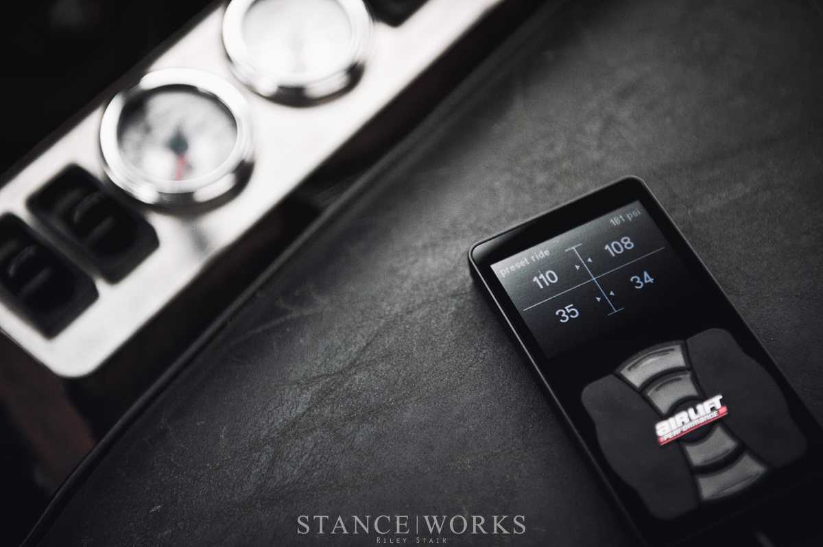
The StanceWorks archives are full to the brim with articles, stories, and helpful pieces, each with history and heart, but many of them fall forgotten to time and the depths of the website itself. Today, we’re diving into the StanceWorks Archives, bringing you one of our favorite how-to articles to date. We’ve always sought to teach our audience something with every article, and our “How-Tos” give us the rare opportunity to focus on such an act. Don’t forget to take a deep dive of your own, there’s no telling what you may find buried within our pages.
Just a few short months ago, Air Lift Performance announced “3H,” their all-new digital air ride management that utilizes both height and pressure based sensors to redefine air suspension as a whole. Ever since, I’ve been anxious to put it to work, waiting to experience a new world of air ride control. However, before I can see just what Air Lift Performance’s 3H system is capable of, I have to install it. What might seem like a daunting task of mounting sensors, brackets, and more, as it turns out, is actually quite simple. Armed with some basic tools, my ’49 Chevy 3100 Pickup feature truck, and the 3H system, I got to work.
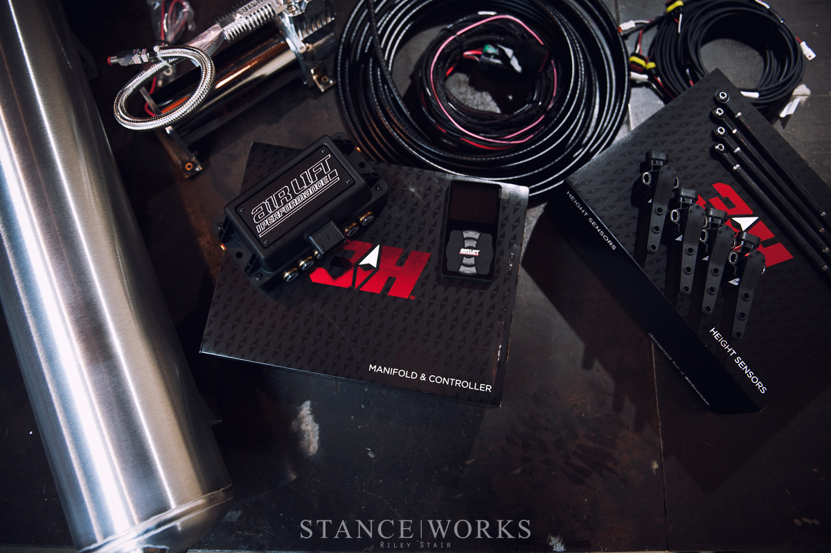
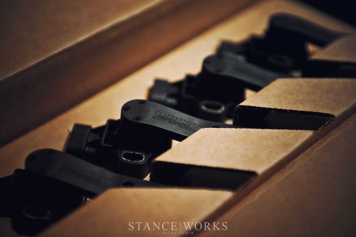
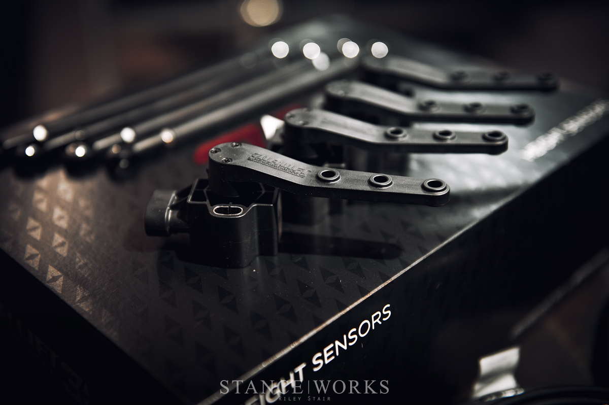
From its very first impression, it’s clear that the 3H system aims to take the “Air Management Throne.” Even its boxing and packaging are top-tier. Everything is very well organized laid out, ready for experienced and inexperienced hands alike. The parts are clearly built to Air Lift Performance’s reputable standard, and even simple details, such as the weatherproof connectors on the system’s harness signify that although the manifold and harness are elegant works of art, they are well equipped to handle the rugged conditions underneath even the hardest working vehicles; which in my application, is a must.
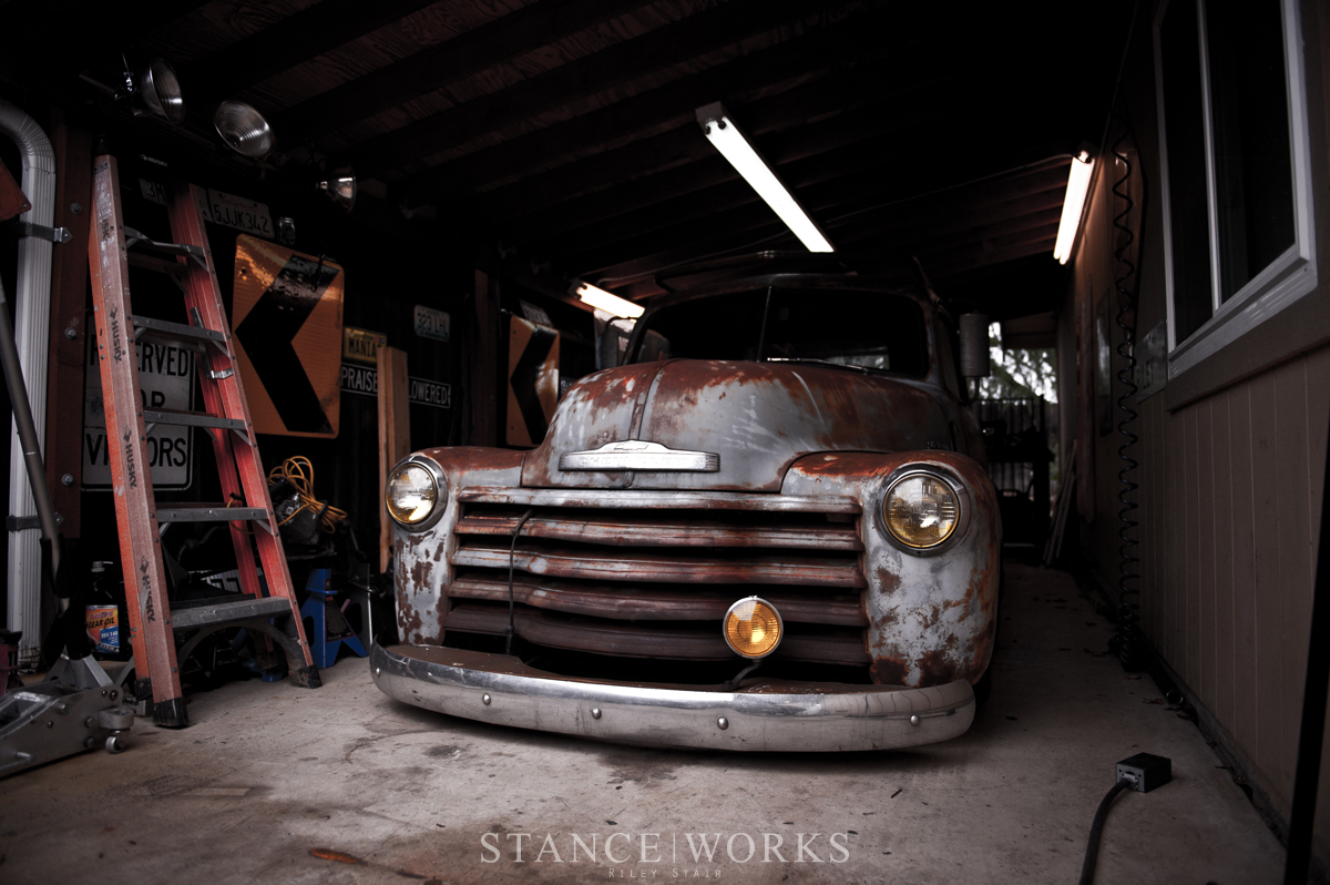
Although my ’49 Chevy has been an ongoing project, since the get-go, air suspension has been an integral part of it. Currently fitted with Air Lift bags and a simple manual paddle-valve system for control, I’ve been eager to upgrade it, and I presume understandably, have been holding out for Air Lift Performance’s latest and greatest. It also seemed to serve as a great canvas for documenting the install process – although it’s not the same underneath as, say, a BMW or Volkswagen, all of the same principles still apply.
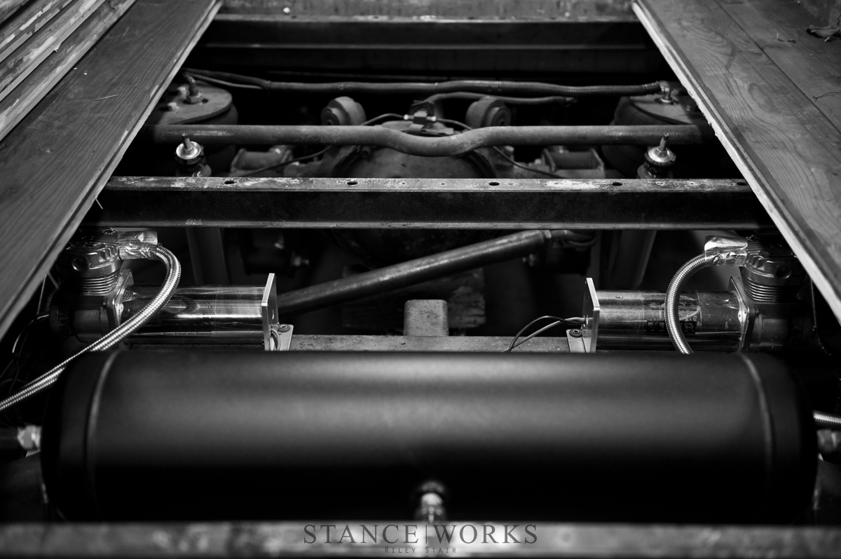
My first order of business, like most people are familiar with, was to get the truck into the garage. With most of the work taking place underneath the truck, I needed to get the truck as high off of the ground as I could manage, and of course, secured on jack stands. In my case, the truck was already bagged, so I got to work and pulled the wood from the bed floor to get a better view of all of the existing air accessories, as well as shed some light on the possible mounting points for the ride height sensors.
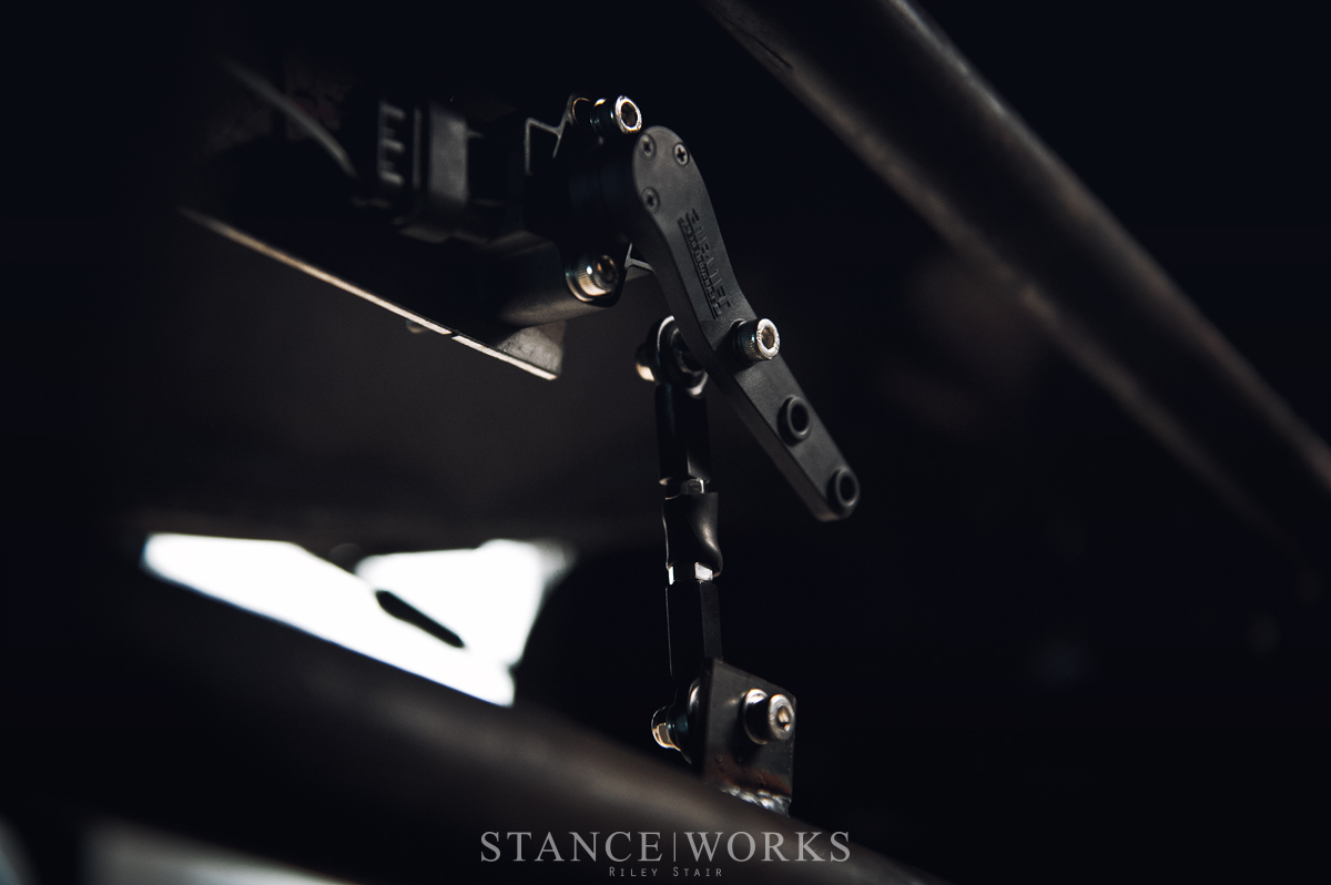
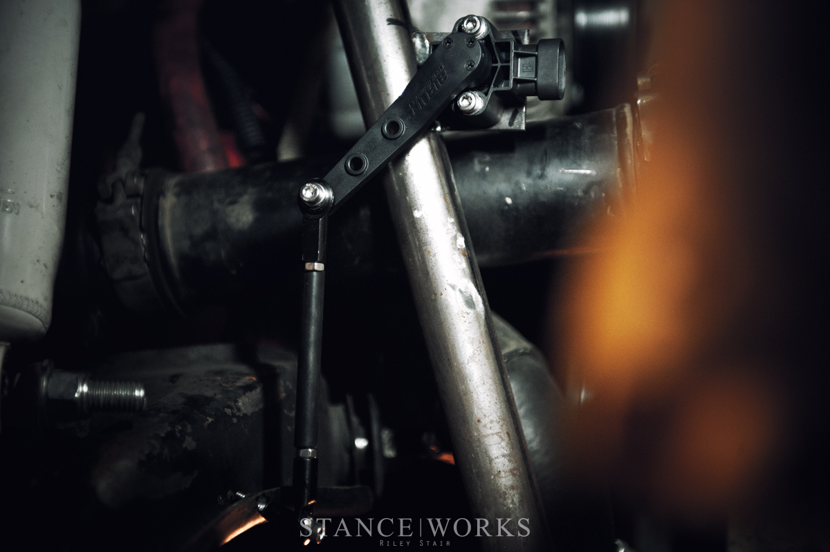
Air Lift Performance’s 3H system utilizes four ride height sensors, which monitor, log, and observe where the vehicles axles/control arms/suspension components are in relation to the body, and how they move. Their inputs are analyzed and interpreted by the 3H’s computer, and changed as needed, with or without driver input. These sensors are universal, and are designed to be mounted on any car, truck, or van. After mapping out possible locations for sensor mounting, keeping in mind that the body of the sensor should be mounted to the chassis, and the linkage to the moving suspension piece, I found the lower 4-link bar to be the best place for the job.
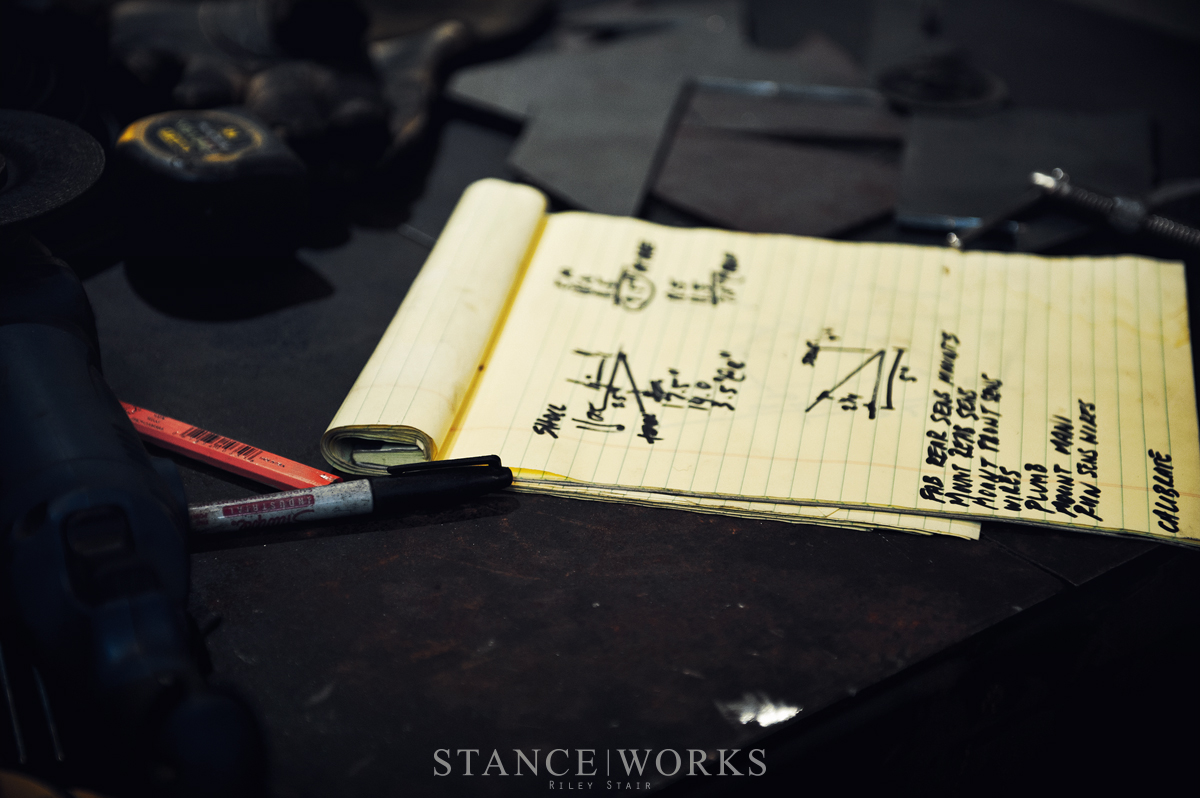
For the 3H install, some simple high-school math is required. The sensors have limited travel, so it is important to crunch some numbers to see how far from the suspension’s body-side mount/pivot point (fulcrum) to mount the sensor, as to not under- or over-travel the sensor through the full range of the suspension travel. Being that the rear of my truck has quite a lot of lift, my sensor location had to be close to the link bar fulcrum. I deduced the exact location by marking a point on the link bar and measuring from the ground, at full droop and full compression, and subtracting the two, giving me the full travel of the link bar, at the chosen point.

For example: 4 inches out from the link’s mount, I made a mark on the link bar. I measured from this mark to the ground with the suspension at full droop, measuring 8 inches. Again, at full compression, measuring 12 inches. Subtracting these numbers gives me 4 inches of travel. After cross-referencing with the Air Lift Performance installation manual, which told me the range of travel for each hole in the sensor arm, I moved my initial mark as needed, to ensure it was within the travel range of the sensor.
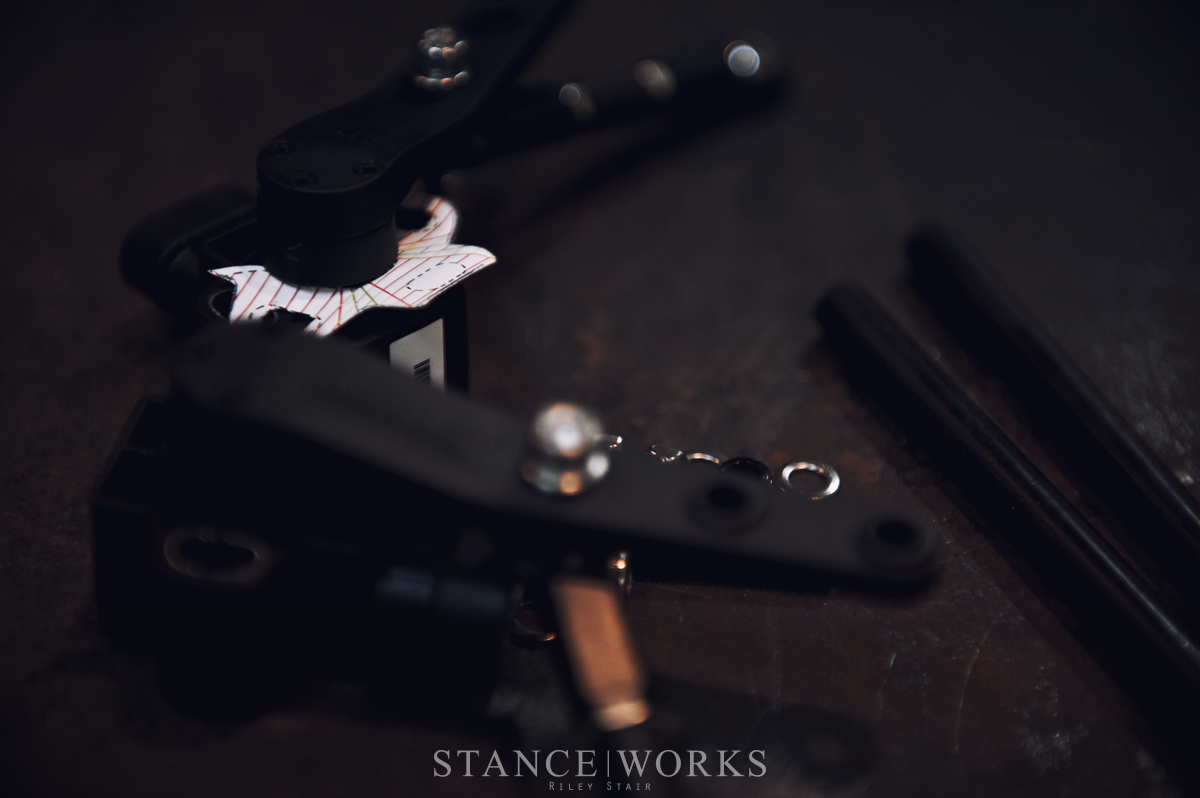
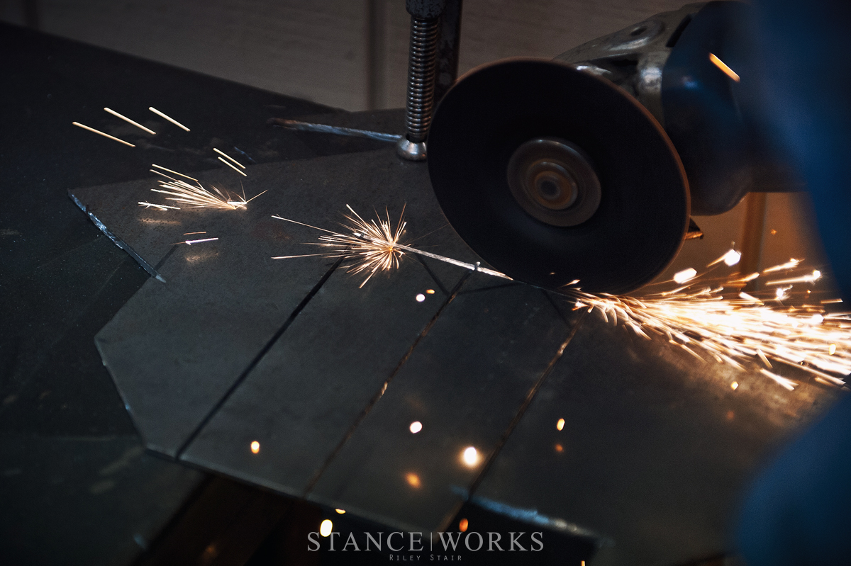
Next up was cutting some mounts for the sensor and the linkage. Once completed, I tack-welded them onto the truck, drilled some mounting holes, and mounted up the sensors for a mock up to ensure my math was correct and the sensor didn’t bind. Using the provided cutout, you can check and make sure that you have the required sensor travel; between 60 and 120 degrees. Once I had that confirmed, I pulled the sensors back off and finish-welded the tabs.
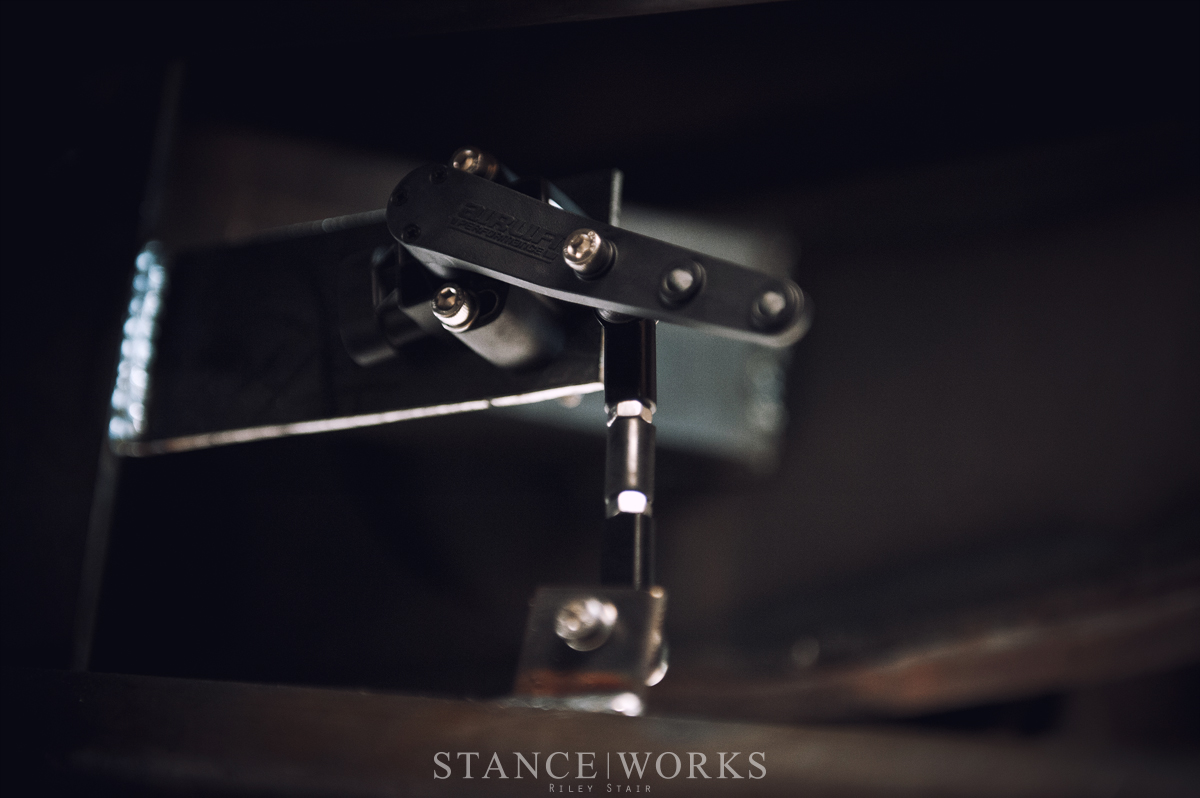
Just like that, the rear was complete, and I moved up to the front, mapping out the sensor location using the same method as the rear end. I found that the front of the upper control arm was one of the best locations for the sensor and linkage, as it was clear of the tire when turning lock-to-lock, and my shock hoop would serve as a good mounting point for the sensor itself. I made up a mounting bracket for the sensor and started measuring, once again checking my range of travel. I chose a point that looked correct based on the trajectory of travel on the arm, and measured, moving further out towards the ball joint to increase amount of travel, and vice versa.

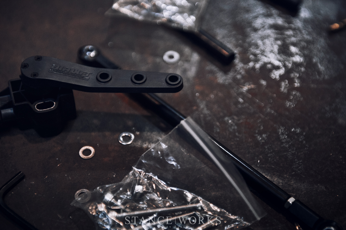
Once the ideal spot was chosen, and measurement confirmed, I tacked on my sensor mount, and drilled a hole in the flange of the upper control arm for a mock up mounting of the sensor and linkage. Once mounted, I cycled the suspension, full droop to full compression, using my template cut from the installation manual, ensuring the sensor landed between the required 60-120 degrees of travel. No more, no less. Once it passed that test, I pulled the sensor back off, finish-welded my tabs, and reinstalled.
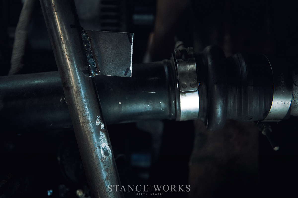
With all four sensors securely installed, the next item on my checklist was to mount the manifold/ECU. Since the truck already had all of the airlines run into the cab, plumbed to the manual paddle valve management the truck was equipped with, the mid-section of the truck was the most ideal location, as all of my airlines would reach without much modification. I chose to mount the manifold underneath the truck, partially to minimize clutter inside the cabin, and keep noise from the manifold at a minimum while playing with the height settings in the truck (who am I kidding, you can’t hear anything over the 12v Cummins engine anyway.)

With the body of the manifold being threaded, it makes mounting the unit a fairly painless process. Originally I intended to mount the manifold inverted, bolted through the floor pan of the truck, but upon reading the instructions, it is clearly stated, it will not function upside down. While it was inconvenient for me, as it forced me to make a plate mount off of the frame rail, it is all for the better, as it will help prevent water from settling in areas sensitive to freezing. With my plate mount made and welded to the frame rail, I mounted my manifold.
Wiring was one of the last things that remained before the truck returned to the ground. Air Lift Performance made the wiring quite simple: the harness comes nearly put together, and includes just about everything you need, spare some side cutters and crimpers. I started by running each corner’s sensor wiring harness from the sensors to the manifold, being sure to avoid heat sources and tucking and zip tying them out of harm’s way. Next, I assembled the main harness, which consisted of adding a couple of supplied inline fuses, for the constant power and keyed 12v source, adding my ring terminals for the constant 12v and the ground (sucking juice straight from the battery), and wiring my compressor signals. Unlike most other management systems that use a pressure sensor in the side of the tank, the Air Lift Performance unit senses pressure from the manifold, and then tells the compressors when to turn on and switch off. With that complete, I plugged the corner sensor wires into their weatherproof connectors on the main harness and then plugged the main harness into the ECU.
Plumbing the unit was the last step on the list, so I pulled the lines from the original paddle valves and gauges inside the cabin of the truck, and rerouted them to their appropriate push-connect ports in the manifold. After some trimming with the supplied airline line cutter, and with a firm push into the connectors, the truck was ready to return back down to earth. The sensors, wiring, and plubming received a final once-over as I set the truck down.
Calibration was the final step before the truck left the side yard to go back to work. I proceeded to fire it up, filling my small work area with smoke and soot, and began following the calibration prompts on the controller. During calibration, I was notified that my sensors were maxing out in their range travel, which, I must say, is a great feature. Remember that 60-120 degrees I was talking about earlier? Well the beauty of this feature is that if you get more than 120 degrees of travel on lift or air out, the manifold notices, and stops the movement. While it was a mild disappointment that I had to crawl back under the truck and re-index my sensors to allow more travel at full lift, I was forever grateful that this feature stopped the movement and calibration and notified me, rather than continue to lift and risk damage to my rear sensors. Other systems on the market aren’t so kind, and tend to snap expensive sensors as they please. With that addressed, I restarted the calibration, and sailed through all of the steps until one of the final steps, which raises the entire vehicle to full lift. At the stock settings the tank pressure is set to 150psi max, which in most applications is sufficient, but due to the enormous weight of the Cummins in the front of my truck, even at 150psi tank pressure it is not enough to lift to maximum height. With a quick dive into the settings, I raised the tank pressure to 200psi, and I made it through the calibration successfully.
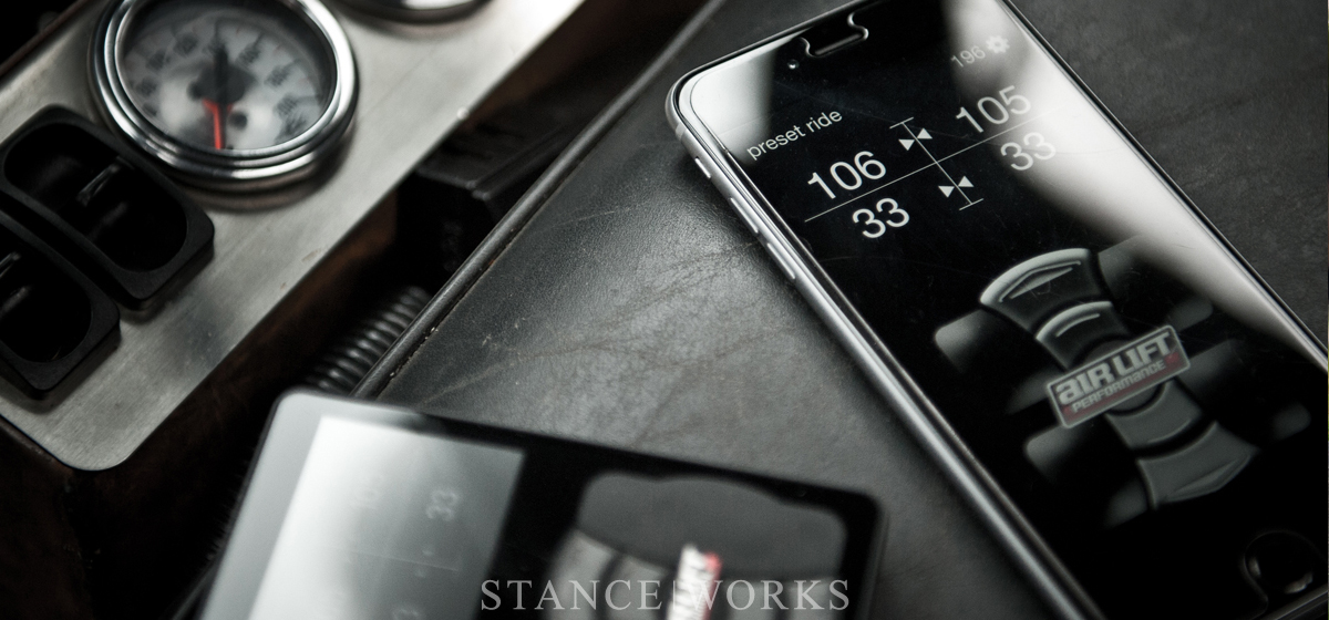
With that, my 3H was installed. I genuinely enjoy the smoothness with which it lifts and lowers the truck, but the most exciting factor perhaps, is no longer needing to manage my paddle valves when I am hauling parts in the bed, if I have a 5000lb car on my trailer, or both. I just press the Airlift button (or tap it on my IPhone app) and go to work. For those looking for the best digital management in the industry, Air Lift Performance’s 3H is unquestionably the answer… and best of all, now you know how to install it.


