 Tweet
Tweet
No, Fluid MotorUnion didn�t start blogging about personal hygiene tactics. This is a whole different kind of backwash.
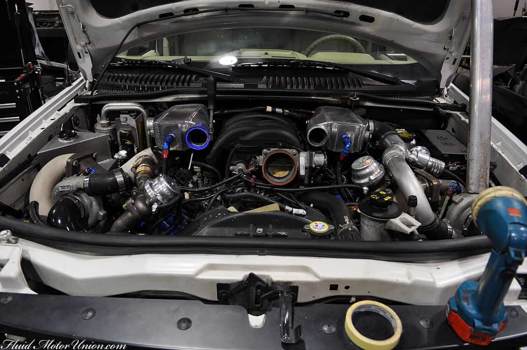
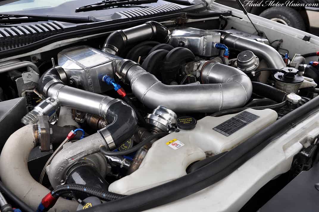
This kind of backwash involves the twin-turbo Ford Explorer that we�ve been fine-tuning. Essentially, the nature in which the piping was arranged caused an unforeseen problem. As the charged air was coming from each turbocharger on separate sides of the motor, some of the charged air was hitting the throttle plate at low throttle angles. Once it made contact with the throttle plate, it would bounce back through the charge piping, reverberating over the mass airflow (MAF) sensor and causing all sorts of issues at those low-throttle angles. That�s the remaining 5% with the build that we discussed on Friday. For us, the easiest way to remedy this issue with the charge piping was to re-do the way the charge piping runs throughout the motor. Instead of each bank working separately and only coming together right before the throttle plate, we plan on running one bank into the other, then over the MAF and into the motor. This should eliminate the backwash and allow us to finish the fine-tuning of the vehicle so we can get it back to Scott in a timely fashion. First things first, though � here�s the engine bay before we altered the intercoolers to accept the new piping routes:
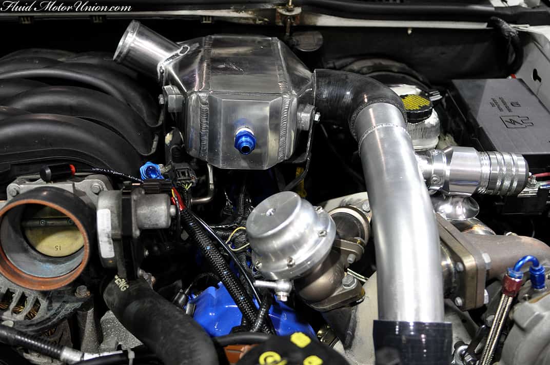
We also moved the blow-off valves (BOVs) to a different location in the charge piping, as we wouldn�t be using that large T-shaped piece of pipe in the new arrangement:
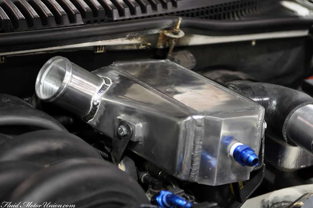
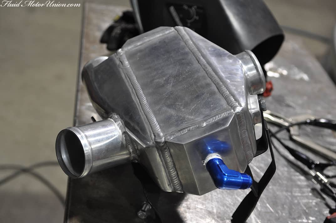
Here�s a quick shot of the driver�s side intercooler. We attached this aluminum pipe to the rear of the intercooler so it can reach over the manifold before running inline with the other bank�s intercooler.
And here�s the passenger side. As you can see from the piping�s angles, the driver�s side charged air will flow over the top of the intake plenum and connect with the passenger side intercooler, where it will run directly to the throttle body.
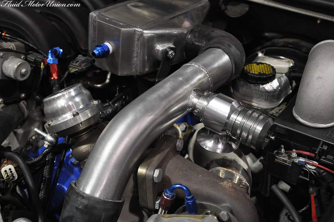
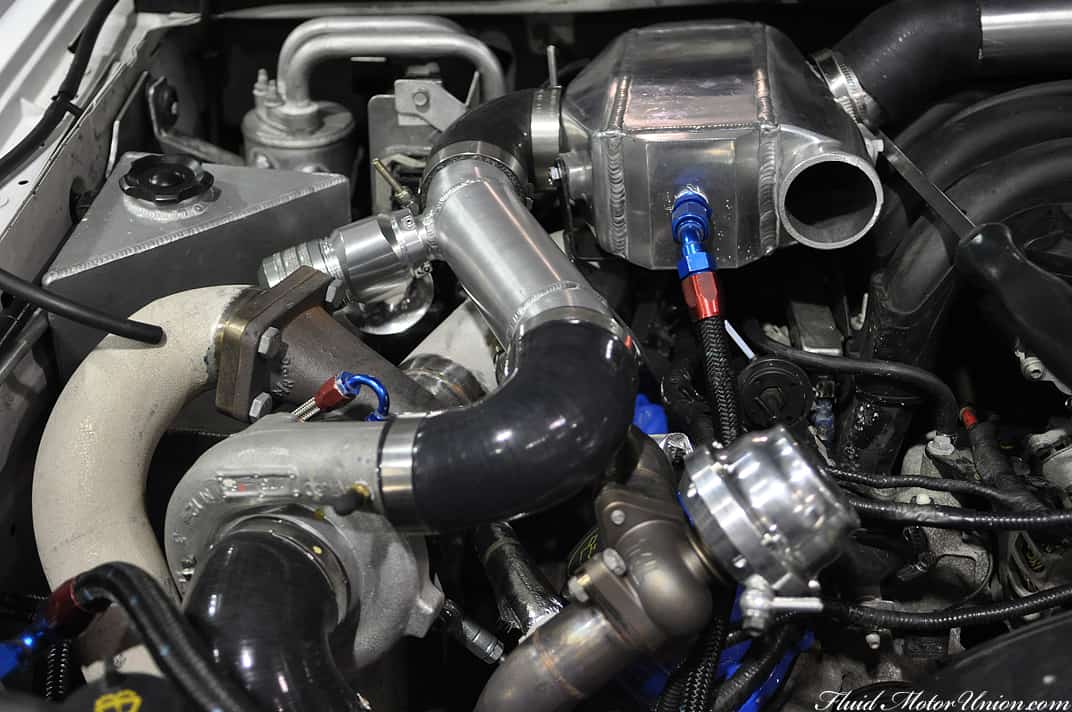
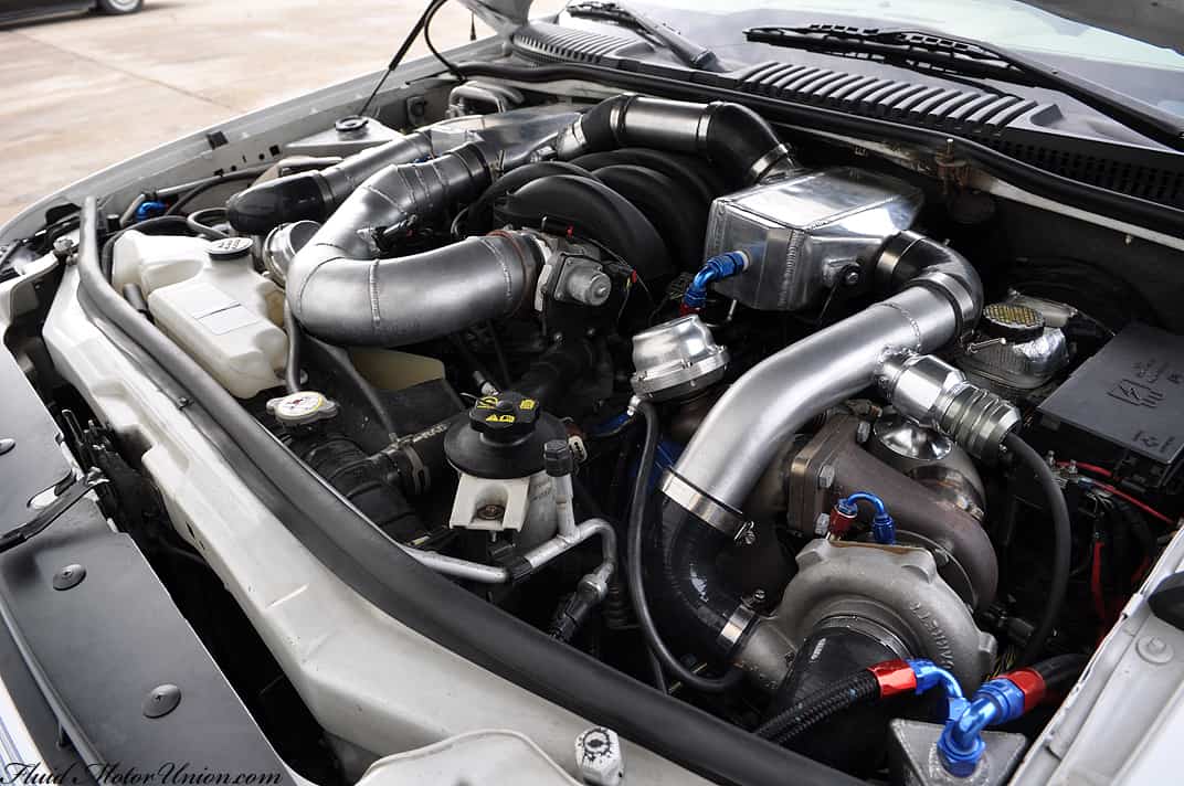
And here�s what it looks like when it�s placed in the engine bay, with the charge piping as well:
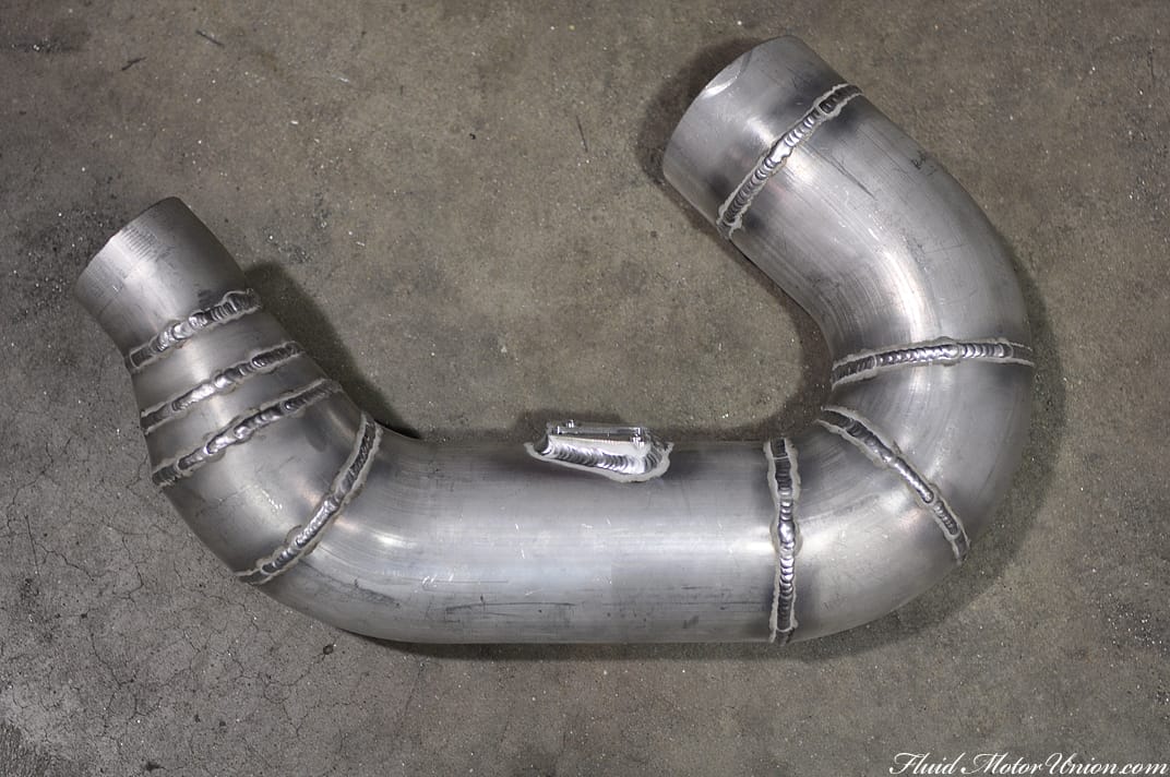
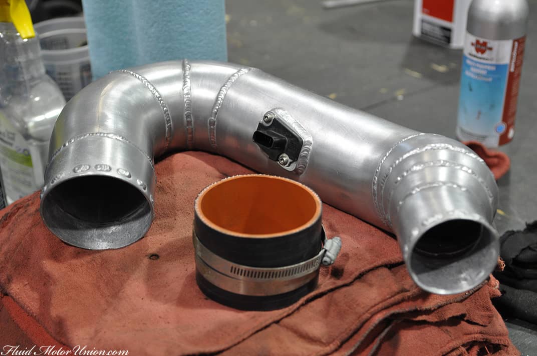
Finally, here is the pipe used to run from the passenger side intercooler to the throttle body and intake plenum. Since the IC and the TB are of two different diameters, the pipe has that neck-up to accomodate the different sizes. You can see the fitting for the MAF connected to the pipe, as well:
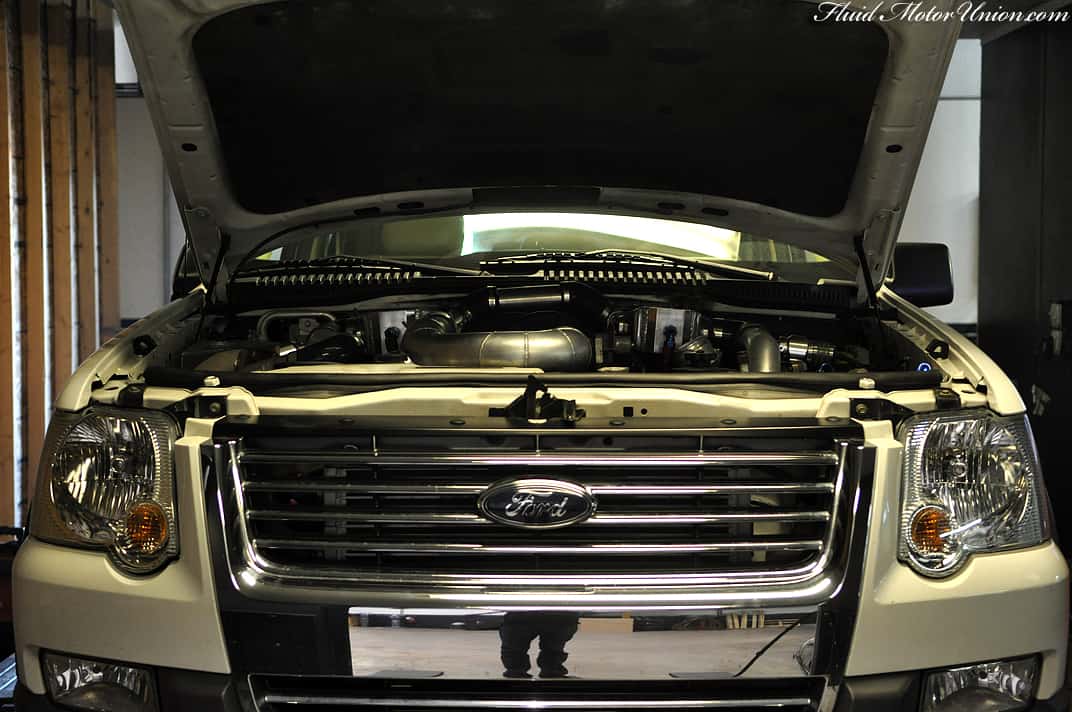
And with a few more pieces connected, it�s all back together!
We�ve had the chance to put it back out on the street, and it�s performing much better than before. Hopefully this will be the last alteration necessary before the first TT Ford Explorer is released into the wild! For now, though, it�s right back where it needs to be � our Dyno Dynamics dynamometer:
This kind of backwash involves the twin-turbo Ford Explorer that we�ve been fine-tuning. Essentially, the nature in which the piping was arranged caused an unforeseen problem. As the charged air was coming from each turbocharger on separate sides of the motor, some of the charged air was hitting the throttle plate at low throttle angles. Once it made contact with the throttle plate, it would bounce back through the charge piping, reverberating over the mass airflow (MAF) sensor and causing all sorts of issues at those low-throttle angles. That�s the remaining 5% with the build that we discussed on Friday. For us, the easiest way to remedy this issue with the charge piping was to re-do the way the charge piping runs throughout the motor. Instead of each bank working separately and only coming together right before the throttle plate, we plan on running one bank into the other, then over the MAF and into the motor. This should eliminate the backwash and allow us to finish the fine-tuning of the vehicle so we can get it back to Scott in a timely fashion. First things first, though � here�s the engine bay before we altered the intercoolers to accept the new piping routes:
We also moved the blow-off valves (BOVs) to a different location in the charge piping, as we wouldn�t be using that large T-shaped piece of pipe in the new arrangement:
Here�s a quick shot of the driver�s side intercooler. We attached this aluminum pipe to the rear of the intercooler so it can reach over the manifold before running inline with the other bank�s intercooler.
And here�s the passenger side. As you can see from the piping�s angles, the driver�s side charged air will flow over the top of the intake plenum and connect with the passenger side intercooler, where it will run directly to the throttle body.
And here�s what it looks like when it�s placed in the engine bay, with the charge piping as well:
Finally, here is the pipe used to run from the passenger side intercooler to the throttle body and intake plenum. Since the IC and the TB are of two different diameters, the pipe has that neck-up to accomodate the different sizes. You can see the fitting for the MAF connected to the pipe, as well:
And with a few more pieces connected, it�s all back together!
We�ve had the chance to put it back out on the street, and it�s performing much better than before. Hopefully this will be the last alteration necessary before the first TT Ford Explorer is released into the wild! For now, though, it�s right back where it needs to be � our Dyno Dynamics dynamometer:


 " - Stretchd8
 " - FittedDownLow

Comment