 That's what I'm affraid of with my project. I haven't hot wired my car before finishing the looms. So if something is interfering, I might just have a lot of un-wiring to do...
-
Oh imagine the horror when you made a mistake somewhere.... That's what I'm affraid of with my project. I haven't hot wired my car before finishing the looms. So if something is interfering, I might just have a lot of un-wiring to do...
-
Thank you everyone for the kind words. heres some more wiring for ya
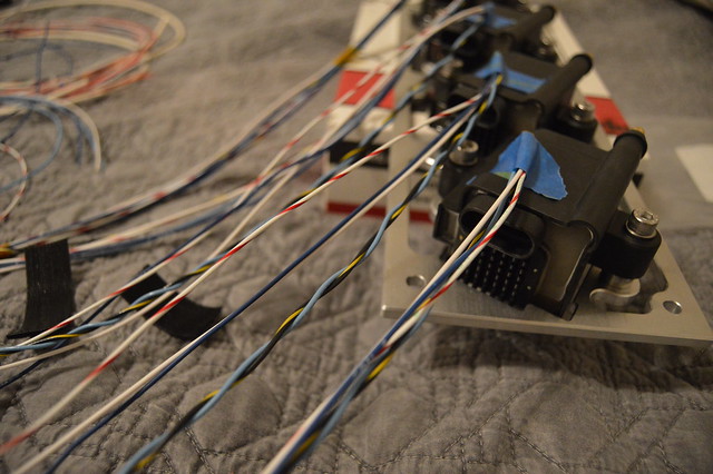
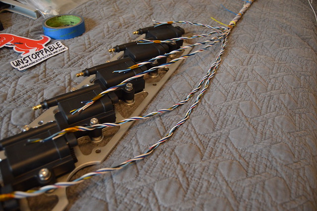
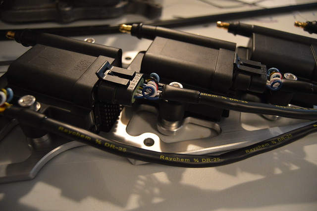
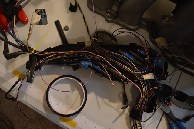
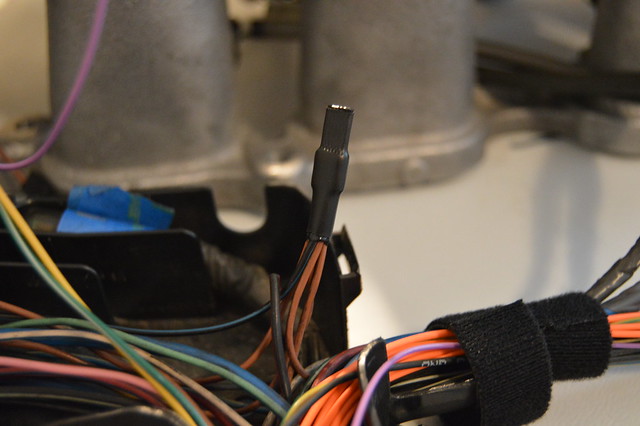
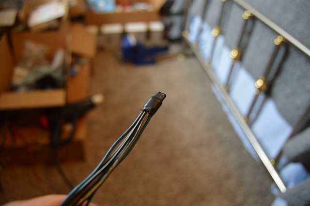
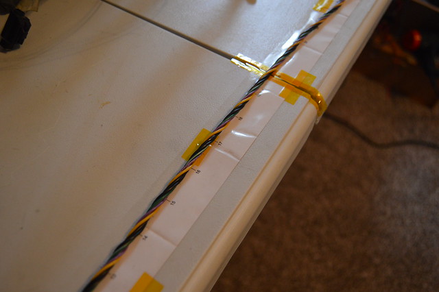
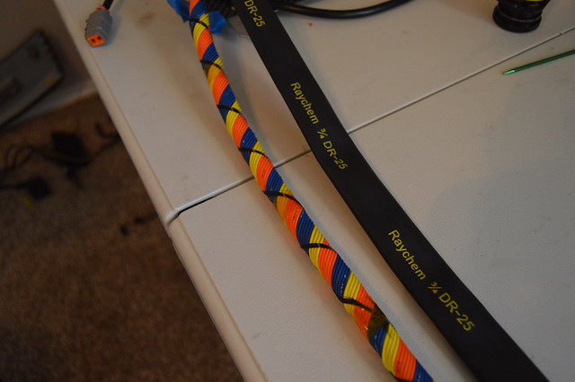
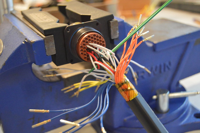
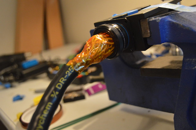
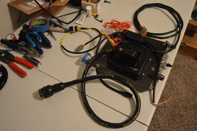
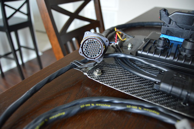
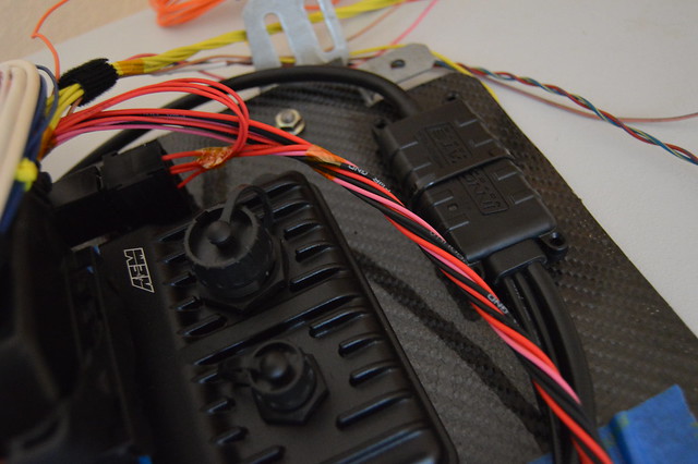
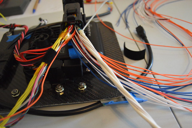
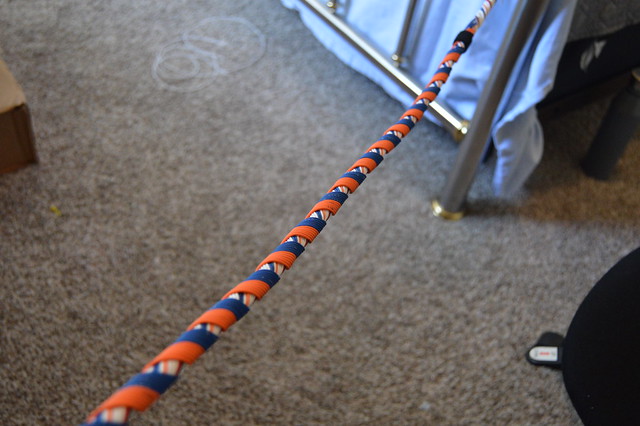
Started on the ignition harness, these coilpacks are 5 wire, one 12V HV power, one HV 12V ground which i used 16ga for, then one signal ground (22ga), a cylinder head ground (18ga), and finally the trigger (22ga).
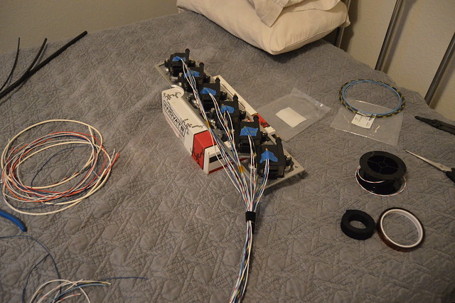
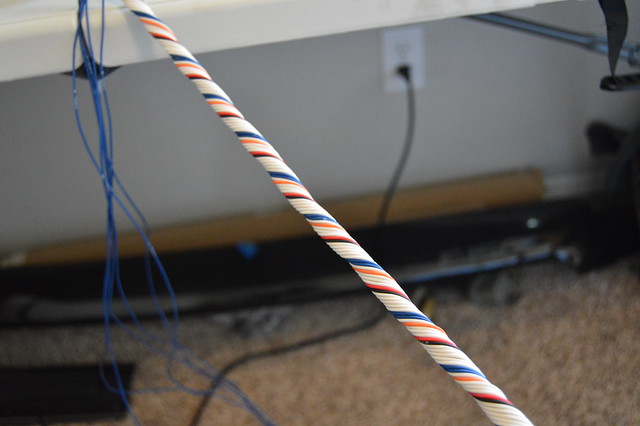
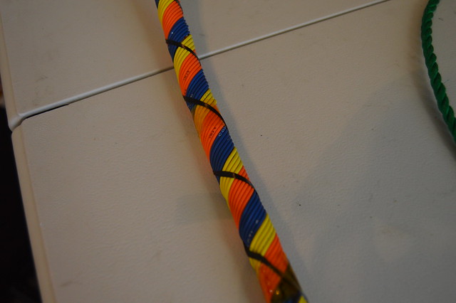
Twisted the high voltage circuits to reduce EMI
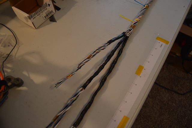
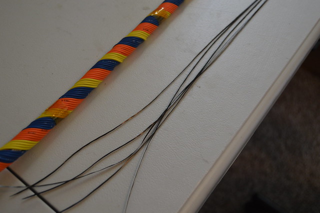
6- 16ga pair circuit core
one layer of 18ga
final layer of signal ground and trigger circuits. Splices will be done at the connector end

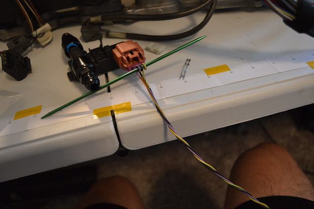
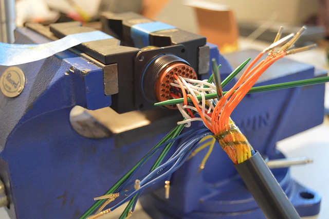
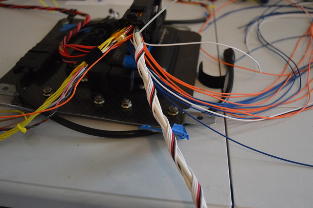
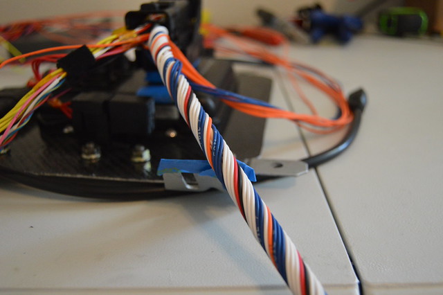
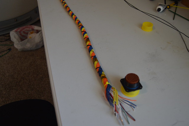
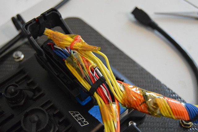
then worked on breakouts and individual branches
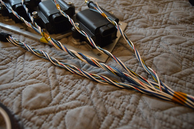
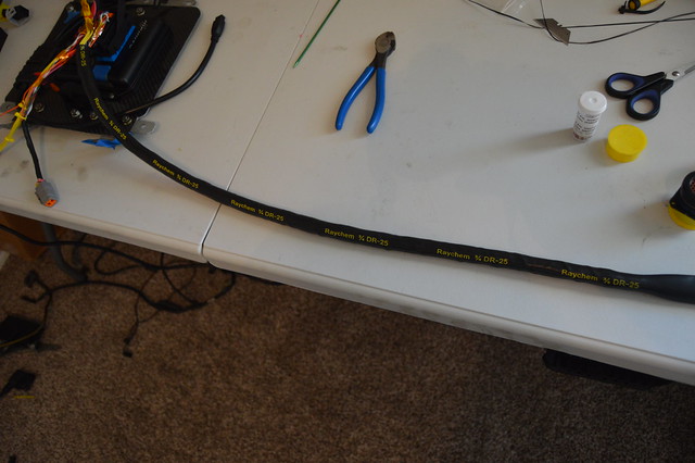
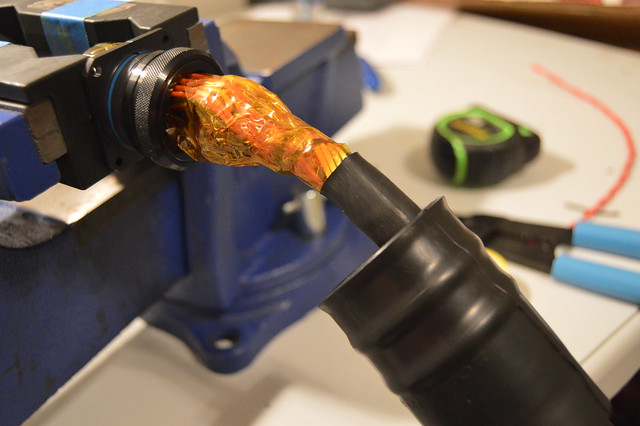
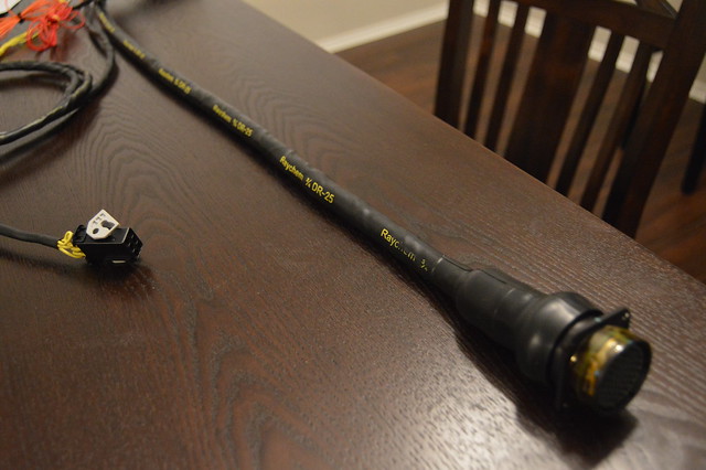
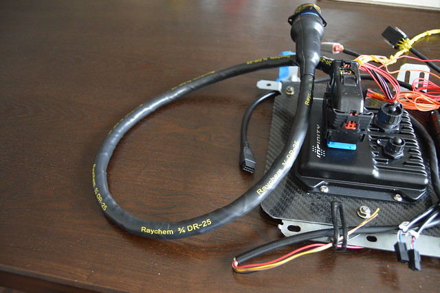
and DR25 treatment with raychem SCL (adhesive lines) used for the transitions and break outs.
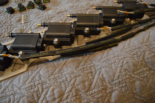
these utilize pull to seat connectors/pins= pain in the ass
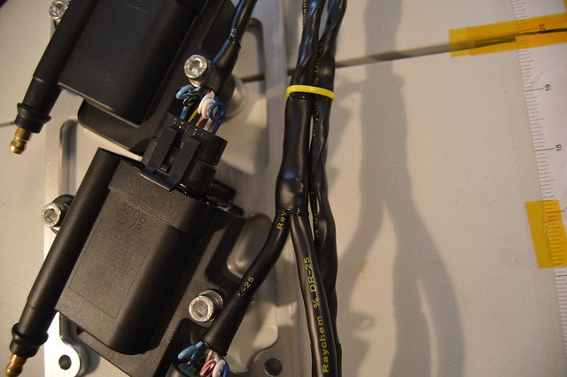
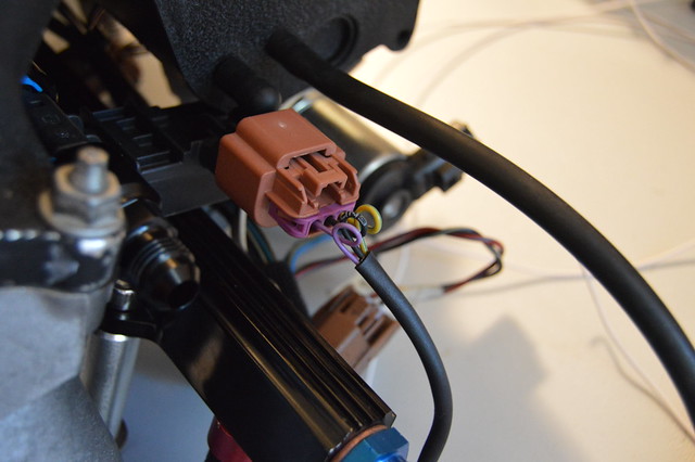
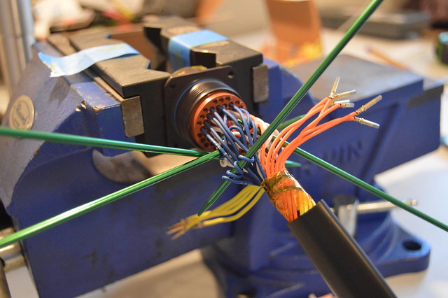
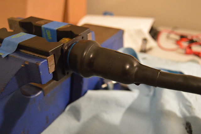
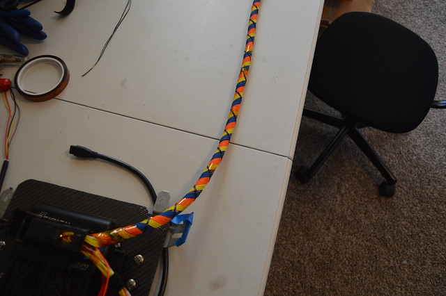
waiting on some more heatshrink and a boot for the main break out but it will be routed behind the FPR and finished off with an 8 pin DTM for the signal ground/ triggers and then a 4 pin DTP for the 12V and ground circuits.

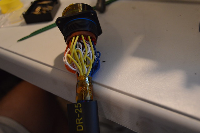
Engine side harness is mainly completed but i totally fucked up the length and decided to repin the entire connector. If you remember the chassis side i ran some circuits too short and this ended up being a pain in the ass causing me to skip positions in the connector. This time i left too much slack and didnt like how the harness was routed afterwords. Already pulled the pins out of the bulkhead and chopped it too the right length. Should have that repinned and booted by this weekend and can start on running battery cable.
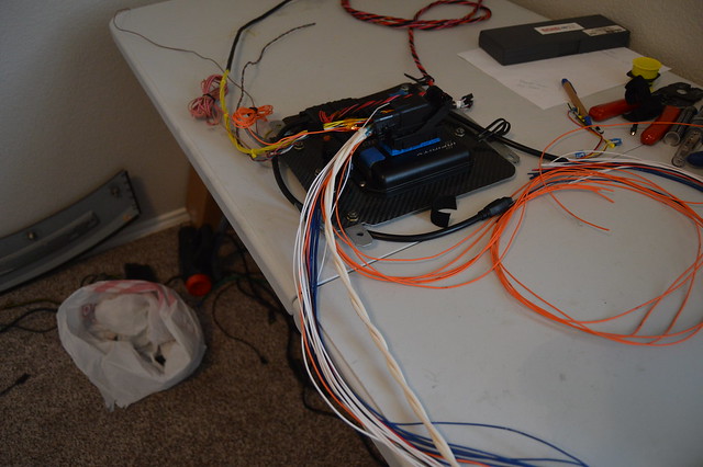
Anways, before we got to the bulkhead i cleaned up all the remaining circuits/ connectors not being used and ran new circuits for my added sensors.
Before-
After-
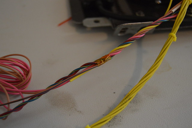
I was investigating the OEM splices when i found they were filled with some sort of dielectric grease
Ended up redoing all the splices except for the injector one as i am waiting on a larger size crimp splice. These are the parallel splices crimped with the indent crimp on my metri pack crimp tool.
I did do a few tests of various wire size and arrangement prior to starting. These are finished off with raychem SCL which is adhesive lined.
And some shots of additional connectors i added. I did reuse some of the OEM wiring here after testing it out via a load test. The copper was also a bright color on everything i reused. Did find some greenish strands in some cases which i threw out.
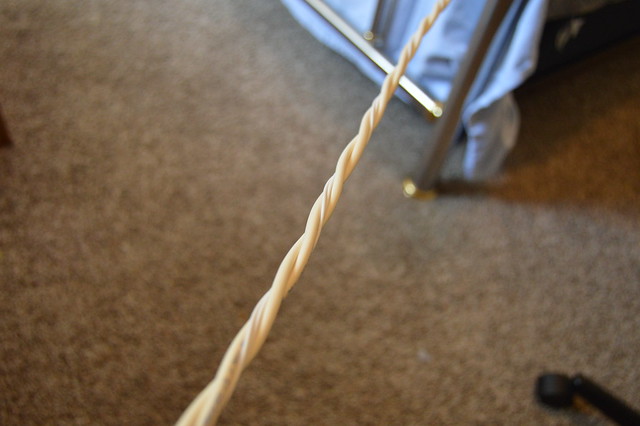
This picture shows off the size of the tefzel (milspec) wiring nicely. The purple circuit (tefzel) is 20 gauge and the black/ yellow-green circuits are 22 gauge. The tefzel wiring is much smaller in total diameter due to the thinner outer insulation. This insulation is also much more difficult to strip and overall much tougher.
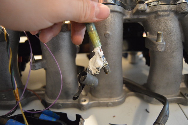
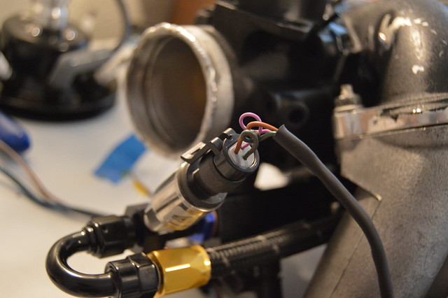
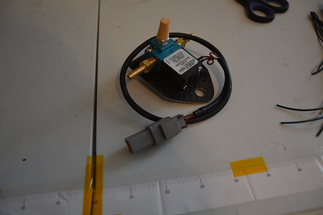
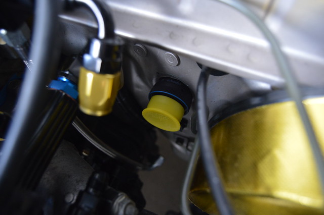
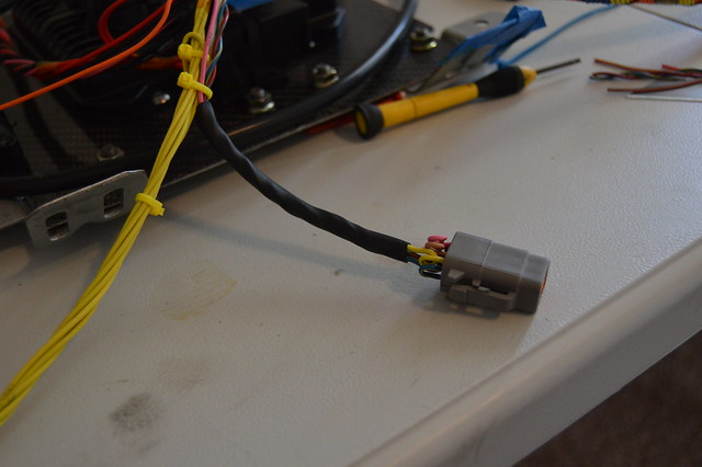
Also potted the coolant temp sensor and wrapped it up with a DTM. It now clears the swirl pot.
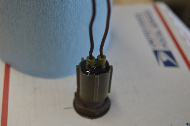
BCS got the same treatment
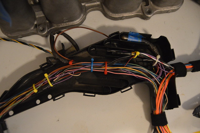
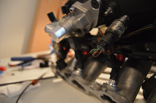
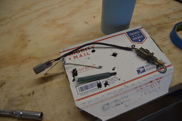
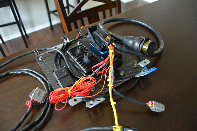
IAT, fuel rail pressure, TPS, and VVTI breakout.
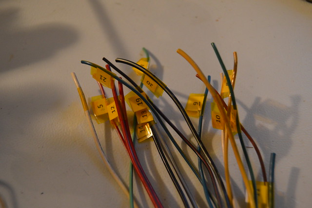
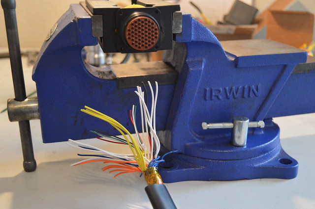
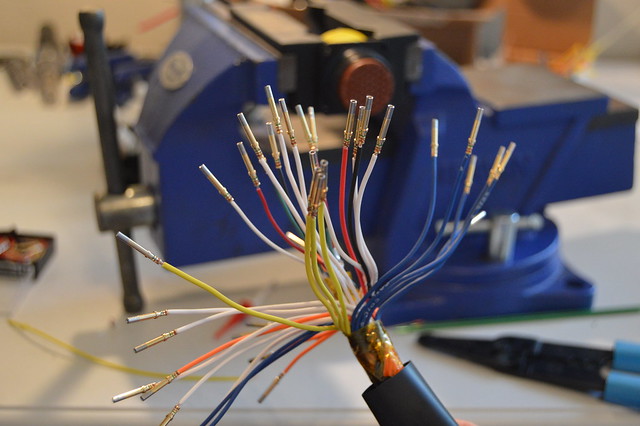
Before cutting off the OEM connectors i numbered all the circuits which made pinning the bulkhead a breeze.
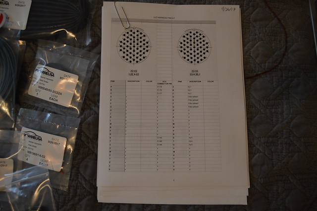
spreadsheet i made using pinouts
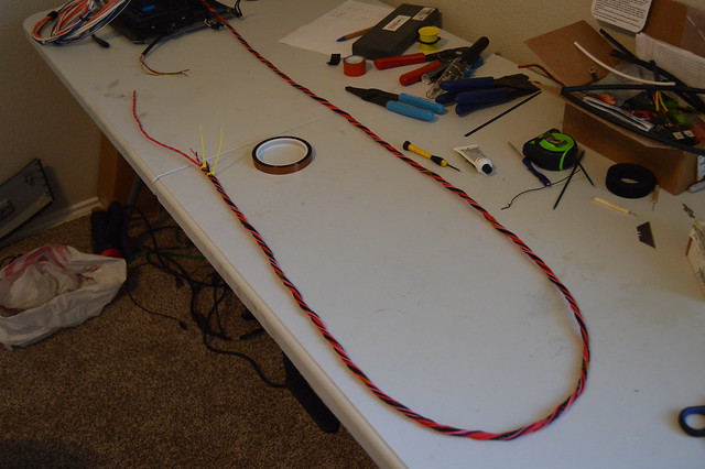
Since i was now pinning this side of the connector in a specific way to obviously match the chassis side i needed to plan out my layers here so everything goes smoothly. Now i know that spending extra time and $ to concentric twist the harness with used wire is not the most logical move but i used it as practice so i dont really care and it will still offer its benefits of flexibility along with compact packaging.
4 shielded circuit core, then inputs, then coils, then injectors
With having such a large core there was just no way i could fill out an additional layer with the number of wires i was dealing with. So i left it at this and heatshrunk it. Also ran 2 additional circuits for possible input/ output expansion in the future.
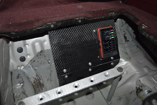
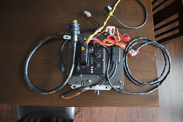
And this is 99% wired up with everything tucked nicely. I have 4 circuits branching to the OEM fuse box which i need to find a home for to supply 12V to the injectors, coils, IAC, VVTI, and ethanol sensor.
Leave a comment:
-
Absolute goals with this wiring, definitely subbed so I can look back at this when I re-do the 911's wiring at some point!Leave a comment:
-
Love all the updates.
As far as the in tank fuel line. Call up some local race shops (or fab shops) to see if they have the tool to make a hard line and bring them your pump assembly to build the line (or rent the tool from them.)Leave a comment:
-
Pulled the dash this morning and installed the harness. Very happy with how it fits. The extra bundled wire is for the boost control solenoid, and ignition switch 12V. I will go through the oem ECU harness sitting on the bottom and steal some switched 12V for use in this case.
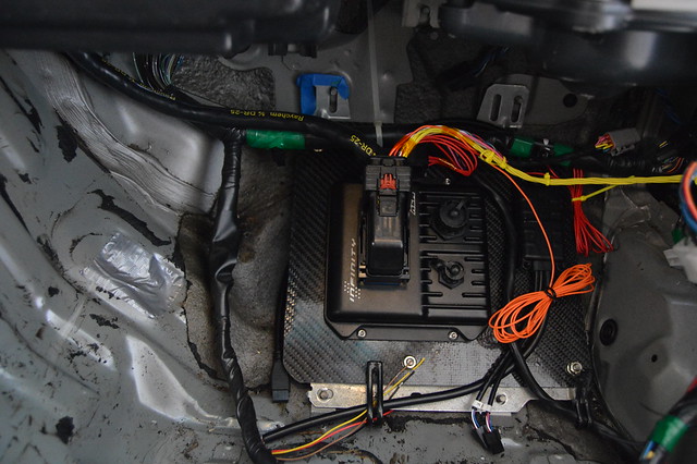
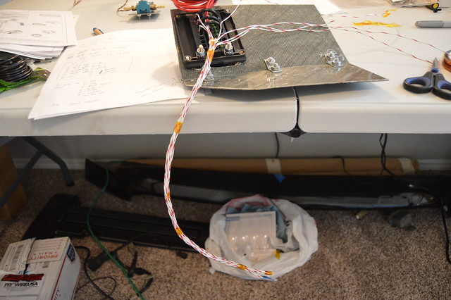
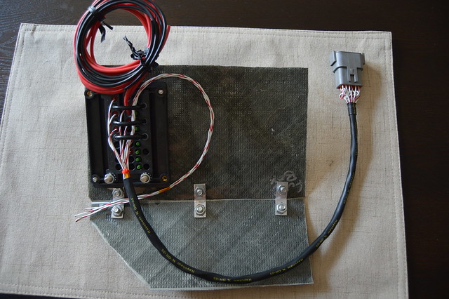
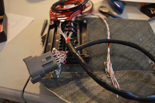
With that done i terminated my fuse box and verified the wire lengths. I have terminated this with 4 total relays (2 extra) and wired the fuses on the outside so i can add additional circuits for whatever. This is being used for the ECU power circuits, cooling fan relay, and fuel pump relay which are both controlled by the infinity. Extra wire on top is for the cooling fan and fuel pump output. The extra 18 gauge circuits are the ECU grounds which will be ran to a bus bar then battery ground.

Leave a comment:
-
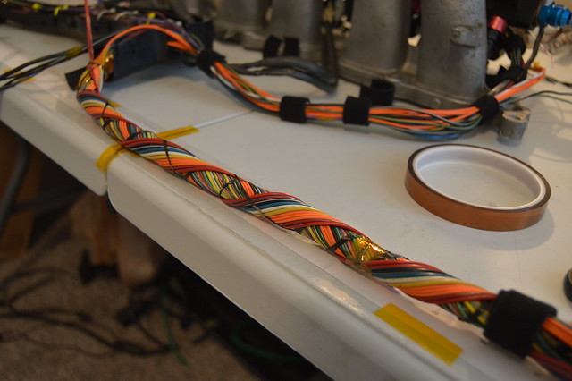
thank you guys! Not really, the main purpose of the kapton tape it to seal the circuits from the epoxy when sealing the heat shrink boot. I have also used it here to secure the harness during the process as opposed to using a zip tie. The tape has very low adhesion and sticks to itself the best. See pictures belowOriginally posted by 190Evan View Post
Finished up the harness and got some other things checked off the never ending list. We will start off with a big order from prowire with everything else i need to wrap up the chassis harness.
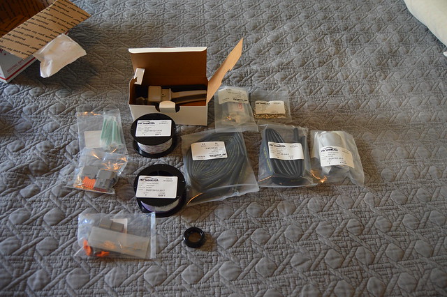
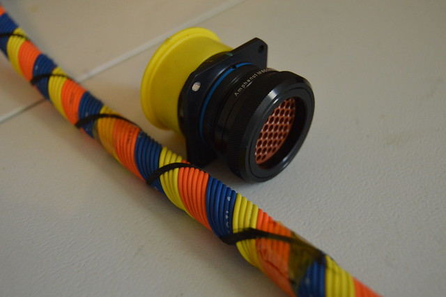
Most importantly this back shell, the heat shrink, and heat shrink boot.
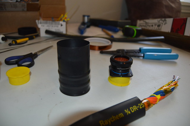
Started off sliding on the heatshrink and shrinking 90%.
Then brought my vice inside and got ready to party
So right as i am getting ready to crimp the first pin i realize that the pins for the milspec connector will not slide into my crimp tool however the pins from the Deutsch connectors slide in with some resistance. Now this is what i get for buying tools this critical used, however i ponied up, found a drill bit barely larger, coated it in grease and drilled (more like honed) the bore on the crimp tool. after this all the pins slid in like butter and i got back to work.
Was really in the zone so forgot to take pictures but started with this. I am using 3mm knitting needles which i got at Michaels for the service loops.
And ended up here. I will say that this is an area i wish looked better but it functions so thats all that matters. Staggering the service loops to look pretty was very hard mainly due to me not leaving enough wire free length. Biggest take away for me here is to leave much more wire length next time.
wrapped in kapton tape ready to be booted
This was fast paced, throw a bead of epoxy on the backshell, heat boot evenly,wipe excess, then throw a bead on the harness side, then heat evenly until we got this
Finished product. At some point i slid on the raychem for my power loom then added a 12 point Deutsch which will be mated to my fuse box.
This was a 55 pin and i only used 38 total pins with 2 shielded circuits dead ended at the connector. I chose to pin it like this due to the injector circuits being too short for other locations. Lesson definitely learned.
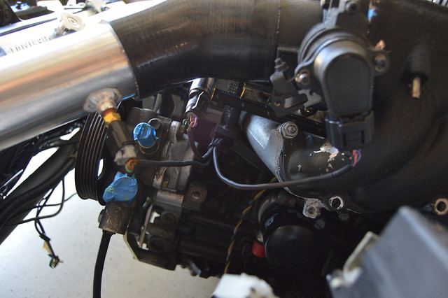
Also swung by my fab shop earlier in the week and got the IAT, breather bung, and second O2 bung welded on while i waited.
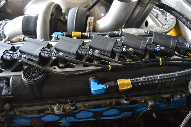
ordered my IGN1A kit from induction performance. Very pleased with this kit as it included everything down to connectors and pins.
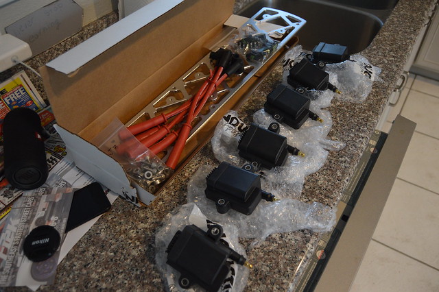
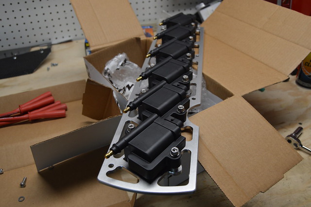
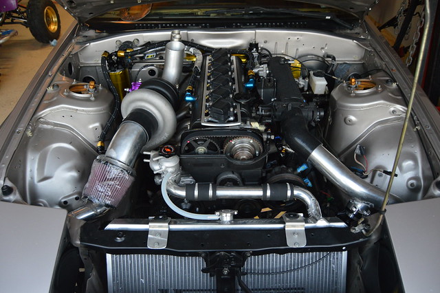
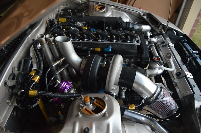
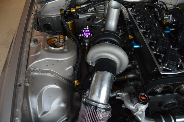
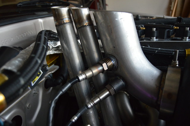
Now i was pretty happy with being able to run the stock hood to fit the engine since it was apparently unheard of, but after much consideration i decided to go with this kit so that i will never have to upgrade again. The other option was OEM USDM coils but the used price of those was about the same as this proven kit. I saw the majority of crazy supras at TX2K running this same setup. I will be running a URAS style vent to clear the front two coils which should help with underhood temps drastically.
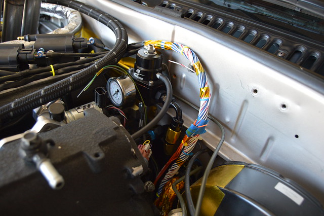
Next up is installing the engine side harness to verify wire lengths for my additional circuits/sensors and then splice in my 5V and 12V along with pinning out the connector. I will also run an ignition sub harness with new tefzel wiring, raychem, etc. My current plan is to get the car running on the stripped and modified OEM harness (verified through load testing to be functional) and then build a mil spec style harness in the near future using new OEM connectors and tefzel wiring. This will be easy due to the detailed documentation i have been making along the way. I need to order a driveshaft, power steering lines/ reservoir, and plug a few coolant ports before we can add fluids, load a base tune, and fire her up!!!!!!Leave a comment:
-
OMG this wiring stuff should be moved to the pron section. It's just so beautiful.Leave a comment:
-
Oh man that is some proper wiring!
Would love to go back through my car and get the wiring looking better but I will never be on the same level!
Love watching this build!Leave a comment:
-
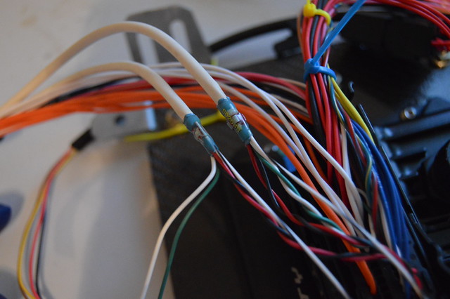
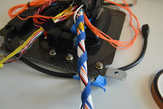
Big wiring update! i have been planning everything out and making sure i have the majority of what i need before starting with this. First needed the shielded cable solder splices to properly ground my shielded cable. I am using the AEM supplied 4 core cables, two circuits for CKP and CMP each, then 2 more for both knock sensors. This leaves me with 2 extra circuits for use in the future. These splices are lined up with the shielded cable so it can be grounded properly.
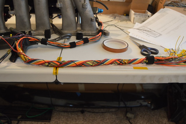
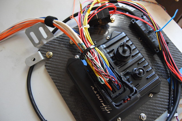
With that being the last piece of the puzzle on the ECU side i zip tied that up.
Now i have the harness separated into a power/ground/ 12V switched loom, a wideband/ boost control solenoid loom, a CAN/ 2 step switch/ shield ground/tach loom, and an engine input/output loom. Twisted up the power/ground side which will run to my fuse box/battery
Ready for heatshrink and a deutsch connector
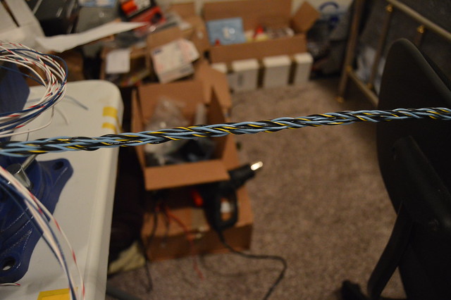
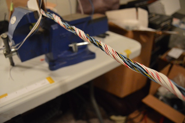
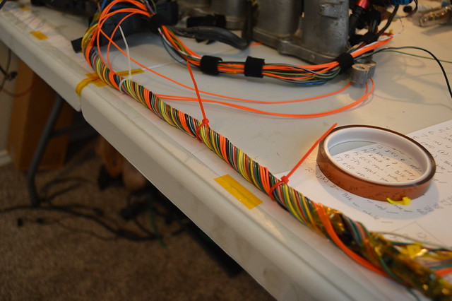
Started the main engine harness with twisting the shielded cables which will be my core here
Now typically you want to wrap layers of 6 at a time and because i have 26 total circuits after the shielded wires i wrapped 2 with the core.
First layer of 6
Second layer of 6
Third layer of 2 filler wires (someone didnt plan correctly)
Third layer of 6 going the other direction now
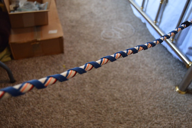
Fourth layer of 6
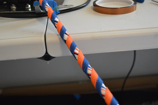
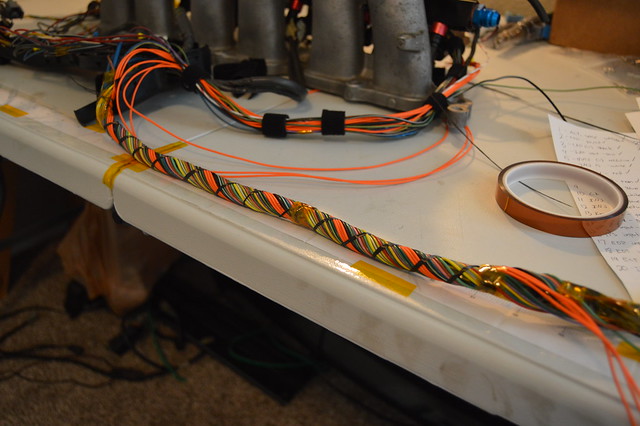
So the industry correct way to concentric twist a harness is to cut all your wire to length (+20%) and then start in the middle and work your way out. It should be done one layer clock wise, then one layer counter clock wise and repeat. Since i have my ECU side terminated already this method cannot be used so i had to do two layers clock wise then 2 counter, and so on. I also had an odd number of total circuits due to the core being large with 8 circuits total (from shielded cable). This left me with needing to use filler wires so after this last orange layer i needed to add an additional layer of 4 more circuits (yellow) to fully fill it out. I do not personally think this is a big deal as i now have 6 extra circuits that i can terminate on both ends without cutting open the harness for future expansion.
I did not take many pictures as it got very difficult to keep the end wound tight while taping and wrapping the last layer. I also cheaped out on spending $30 on a 1500 yard roll of lacing cord so i pulled threads out of the rolls of raw carbon fiber i have.
6 filler circuits pinned on the ECU side and wrapped in kapton tape
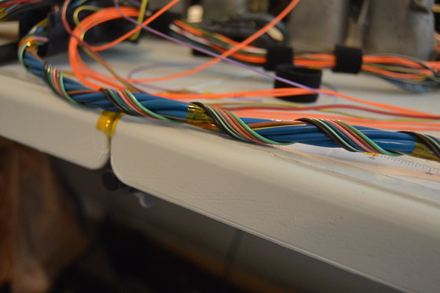
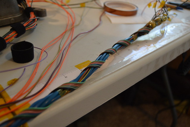
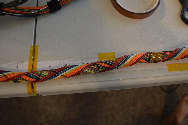
All done and perfect length now awaiting heatshrink. This is a 40 circuit total with two 4 conductor shielded wire bundles core measuring .55" in total diameter. I am pretty happy with how this came out for it being my first time. I will be running the modified OEM harness on the engine side but now want to badly build a harness from scratch with new toyota connectors over the winter. This should only cost me a few hundred dollars since i am now tooled to do this.
I was also itching to use my DMC crimper so i terminated this 6 pin DTM which will be used for my CAN, shielding ground, tach output, 2 step switch, and 12V switched power for the AEM UEGO.

Now i have to order my heatshrink and boot before terminating the bulk head. I am also ordering my ING1A ignition system before starting on the engine side. Still need to route and terminate new wires for my EOT, IAT, EOP, FRP, ECS, and MAP sensors. Also ran into an issue with the swirl pot setup the shop made me. There is just not enough room to plug the ECT connector in so after talking to the shop they want to pot the ECT sensor which i thought was a great idea. Basically they will remove the pins from the connector, plug them in on the sensor, then fill the sensor socket with epoxy. A DTM connector will then be added a few inches further down the circuit. Something i can do but will let them handle it since its kinda their fault. They need to weld on an IAT bung, -10 bung, and second UEGO bung anyways for me. Waiting on the correct fuse box to arrive and then i can start on terminating that.Leave a comment:
Leave a comment: