Announcement

Collapse
No announcement yet.

Champagne Realities RX7

Collapse
X
 
  • Filter
  • Time
  • Show
Clear All
new posts

  • danny33
    replied
    Car is running smoothly currently and i am waiting on a TPS sensor before i am able to drive it. Copy/paste update below from Norotors.

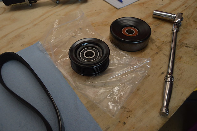
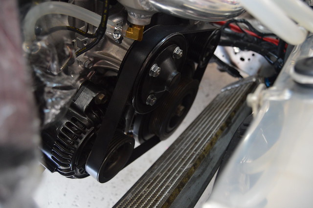
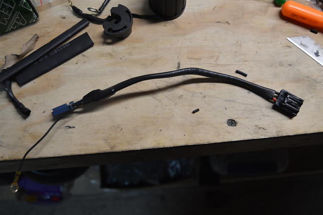
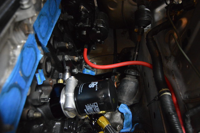
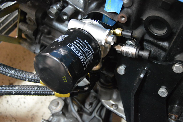
    For sake of time and money i ordered this PS delete kit from driftmotion and got that installed.


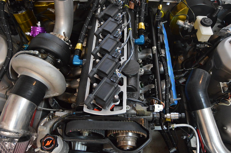
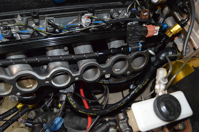
    Ordered heat range 7 plugs and gapped them accordingly. installed plug wires and finalized ignition system install.


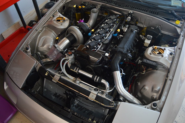
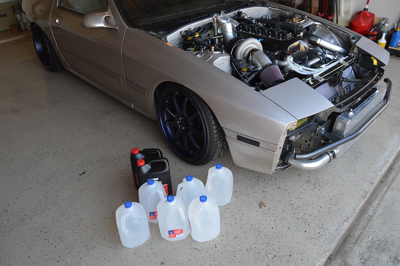
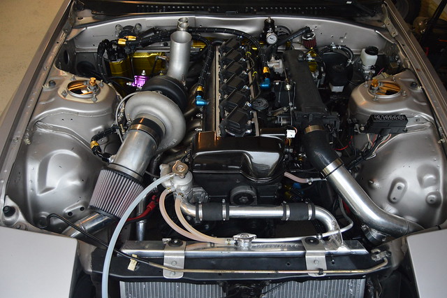
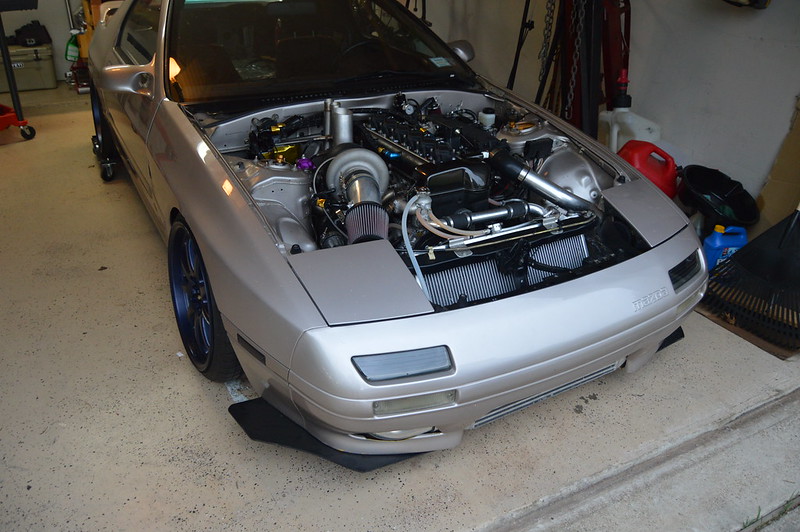
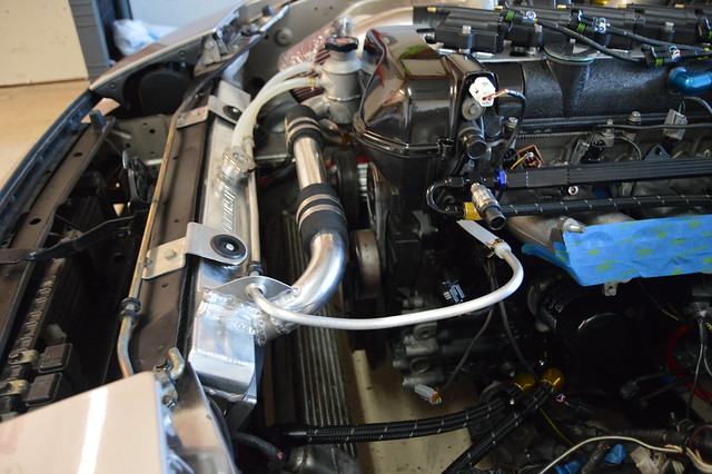
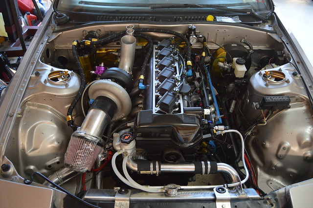
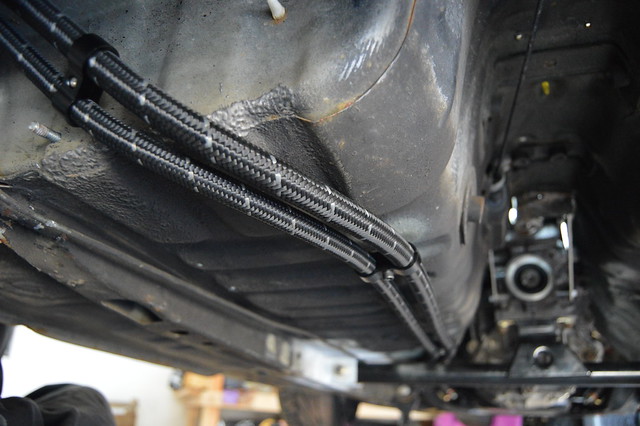
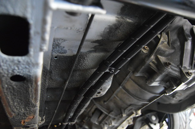
    Finally fully plumbed, wired, and awaiting fluids.


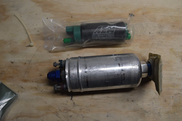
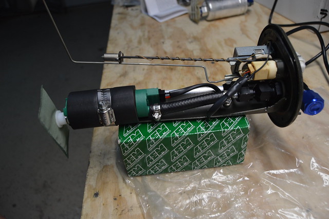
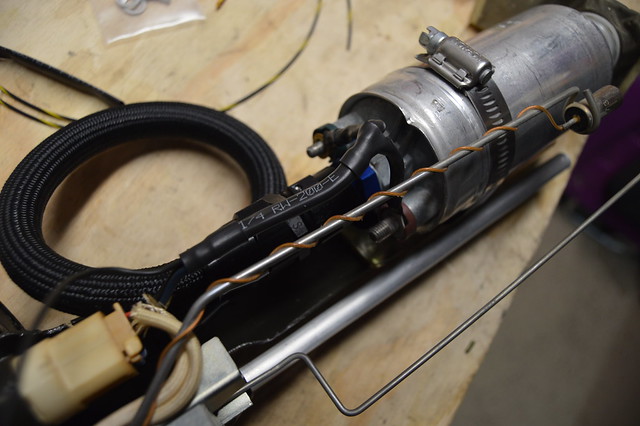
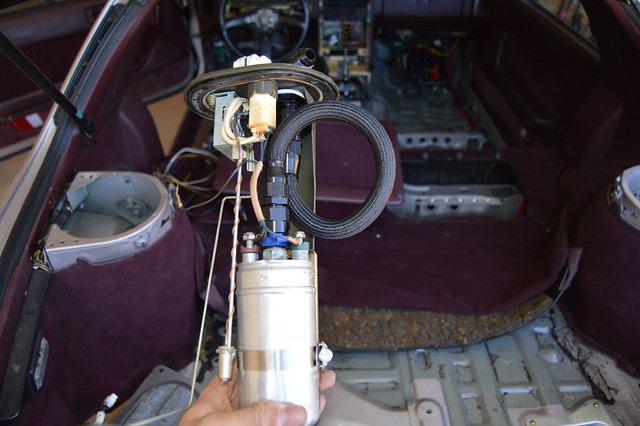
    Also ended up switching last minute to AEMs new E85 320lph pump due to struggling to fit the 044 and the looped line into the tank. I ended up not being able to fit the 044 inside the sump chamber at the bottom of the tank, and during that ended up kinking the PTFE line. Ordered up this AEM and rewired the pump and got everything installed. This AEM actually flows more than an 044 and is also more consistent throughout higher fuel pressures per Dsports fuel pump shootout.


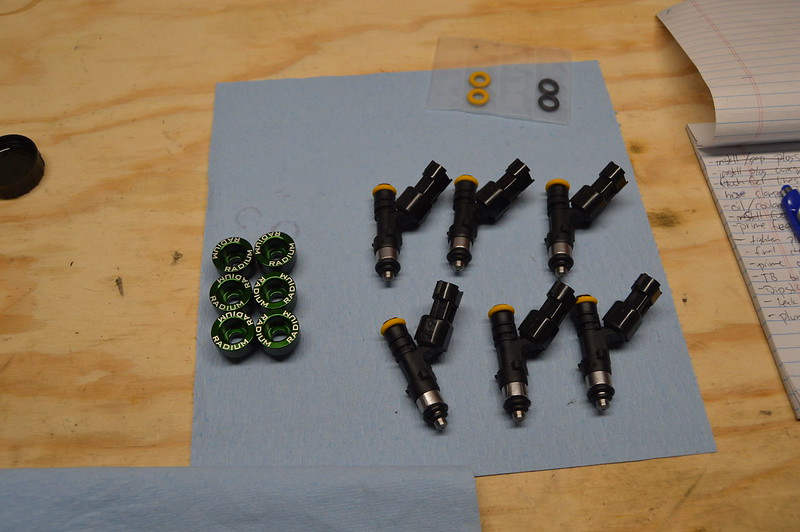
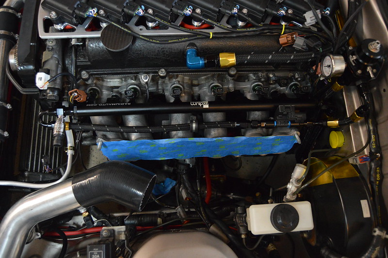
    After installing the pump i primed my fuel system to flush the lines and found a large fuel leak at the number 1 injector. Havent torn it down yet but it appeared to be coming from the O ring which seals the top of the injector to the adapter which then inserts into the rail. Figures out of all the fuel fittings i have assembled the only thing that leaks is what i did not check. I actually never bothered to check those O rings or even remove the adapters.

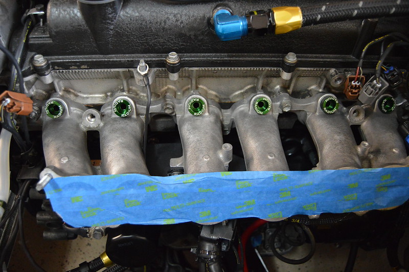
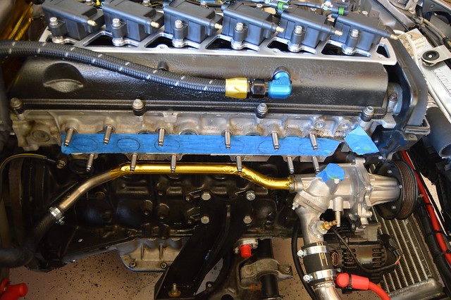
    Fuel leak was caused by drift motion using copper crush washers on ORB fittings. I had them really things tight but they still leaked and i also didnt like how the plug on the rail protruded 60% into the bore of the rail. Radium rail installed and this thing is badass and such a high quality piece. injectors got all new O rings as well.


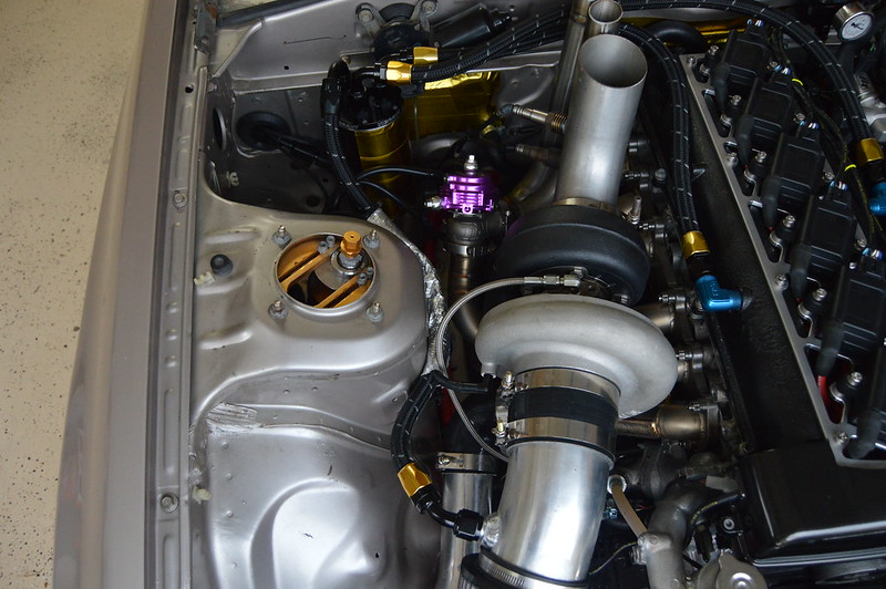
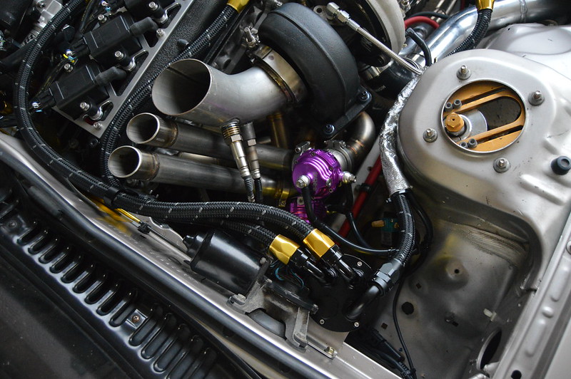
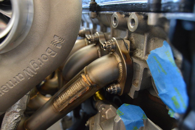
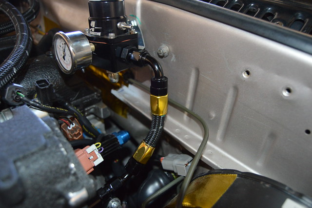
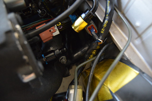
    Last plumbing work was for the wastegates. I wanted to keep it tidy and got the job done using 3 tee fittings. May rework it to shorten lines a little more if possible. this is set up per AEM recommendation for max boost/ response and to run spring pressure when EBCS is off.
    [img width=800 height=532]https://farm5.staticflickr.com/4649/28250328849_137cbb8f90_k.jpg[/img]

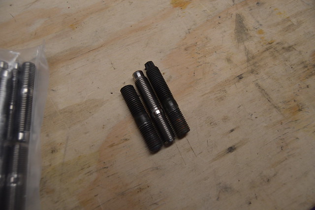
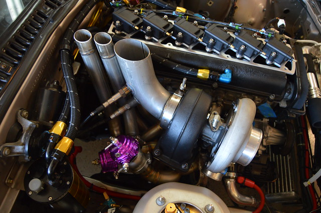
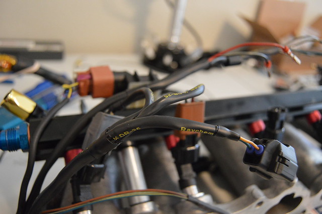
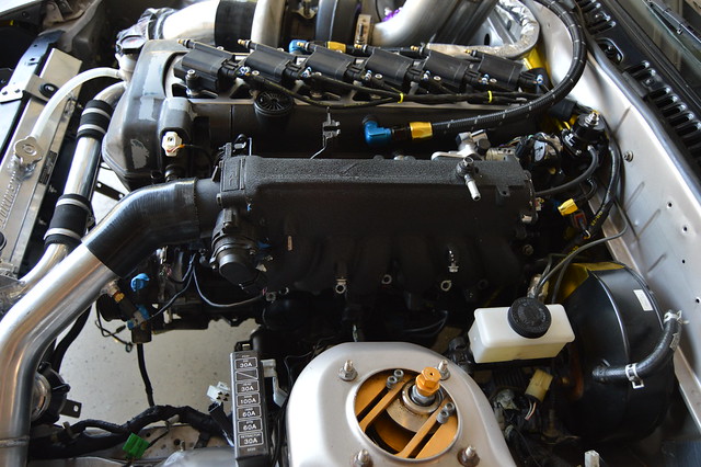
    Realized how expensive t bolts/ constant tension stuff was but read through a bunch of reviews and found a great deal on these t bolts on amazon.
    [img width=800 height=532]https://farm5.staticflickr.com/4627/28250328469_0f86d33594_k.jpg[/img]

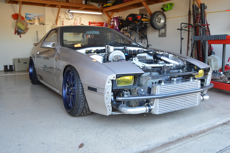
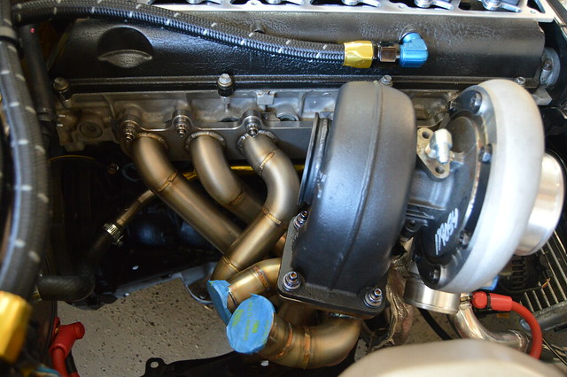
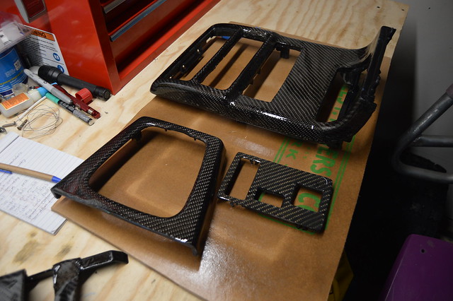
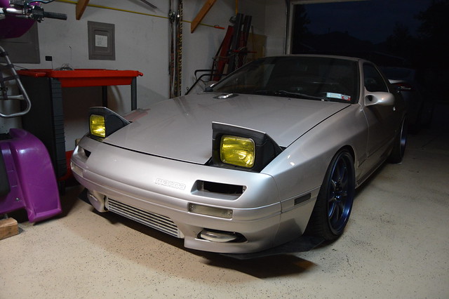
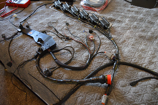
    Grabbed my FTPs when i was home for the holidays as well and threw them back on. I like this look again
    [img width=800 height=532]https://farm5.staticflickr.com/4716/25158443807_b3fdbf7221_k.jpg[/img]

    I wanted to update this with some info on the last pieces for anyone referencing this thread. As stated earlier, after smoothing out some cold starts and idle tables on the tune, we noticed that my throttle % would read negative when snapping the throttle. Turns out the used manifold i bought to delete the aristo DBW throttle had a 2JZ GE TPS sensor installed which rotates backwards. I have a new sensor on order but it wont be here until next week.

    For a throttle cable, i bought a $22 FD RX7 cable from summit and cut the throttle end off and then cut the cable to length. After i did this, i crimped the threaded housing end back onto the cable and then used a set crew type cable end lug. This worked well as the firewall clip and throttle pedal clip were all the same as the OEM cable.

    For a driveshaft, i had a custom one made by a local shop - fort worth gear and axle. total distance between output shaft and pinion flange was 34-7/16". Most driveline shops order slip yokes/ flanges from powertrain industries and for a CD009 you will need a 3503-323 slip yoke and the turbo II pinion flange 2602-41. For reference, i am using a TII housing with a Kaaz 1.5way LSD. An 8.8 kit with gearing to match the CD009 is on the list. I already have a complete 8.8 LSD waiting for me to pick up.

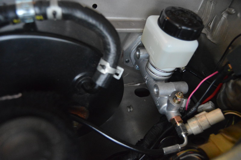
    Clutch setup is an ACT sprung 6 puck 350Z clutch on the collins kit with flywheel. I used the 350Z slave cylinder with the 350Z OEM sized master cylinder from Wilwood in 5/8. Stu kelley firewall adapter and trimmed Mazda clutch pushrod. I had a custom clutch line made by chasebays @ 33" length.

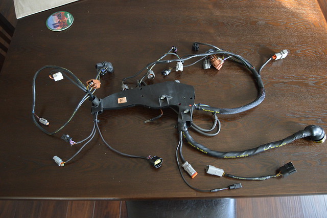
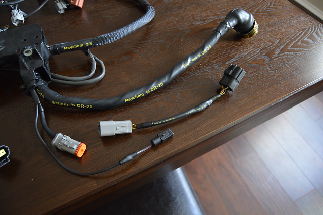
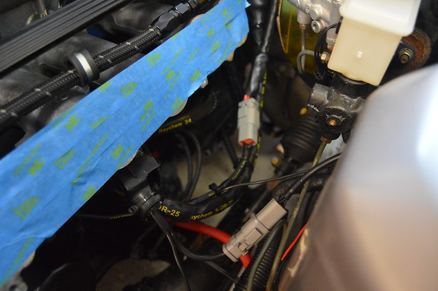
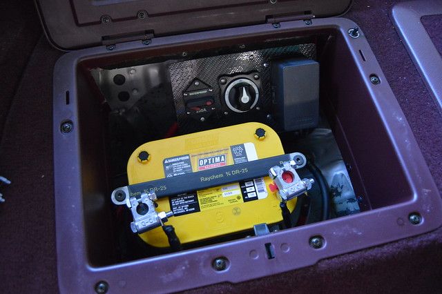
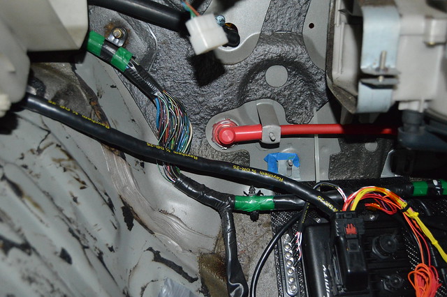
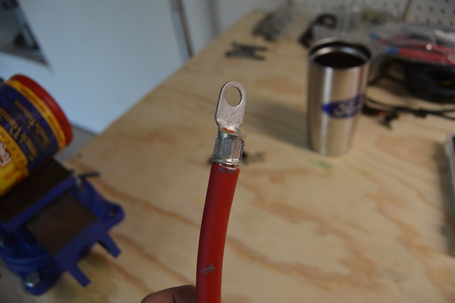
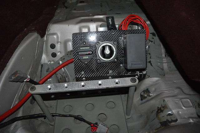
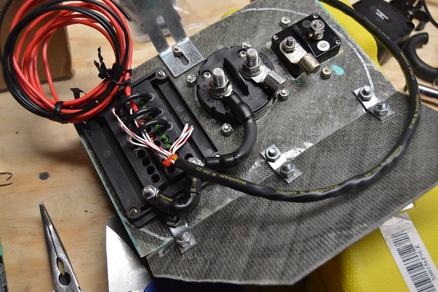
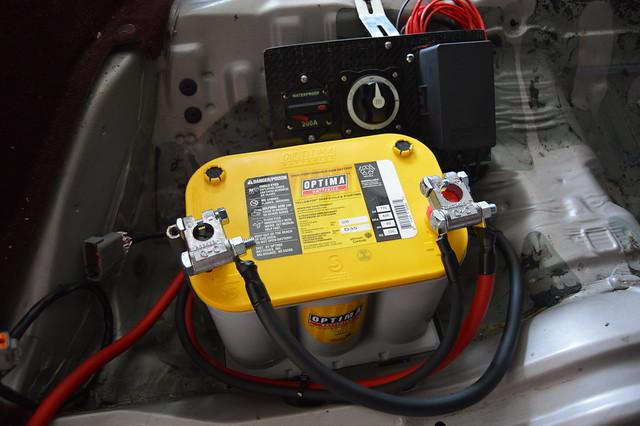
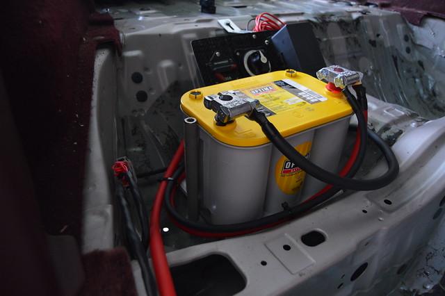
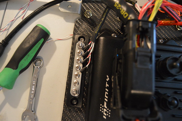
    I did have some issues with voltage drop from the Mazda chassis wiring i tapped into in the engine bay. I ended up adding 2 additional fuses to the mazda underhood fuse box using terminals i harvested from other connectors. I then ran 2 relays underhood to supply power to the VVTI, IAC, and injectors. The other relay feeds the cooling fans to reduce any voltage drop from the relaybox mounted in my passenger cubby.

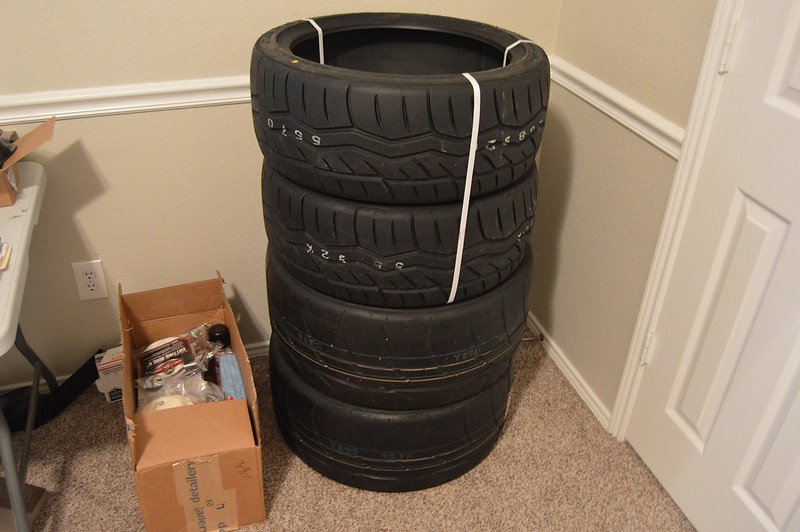
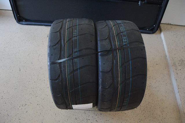
    I will be mounting tires soon and will be running Falken Azenis RT615K+ in 225/40/18 in the front and Nitto NT01s in the rear @ 265/40/18. Before the car is truly roadworthy i need to do front control arm bushings, order the Hinson sway bar spacers, and replace the front wheel bearings using the mazdatrix stuff.

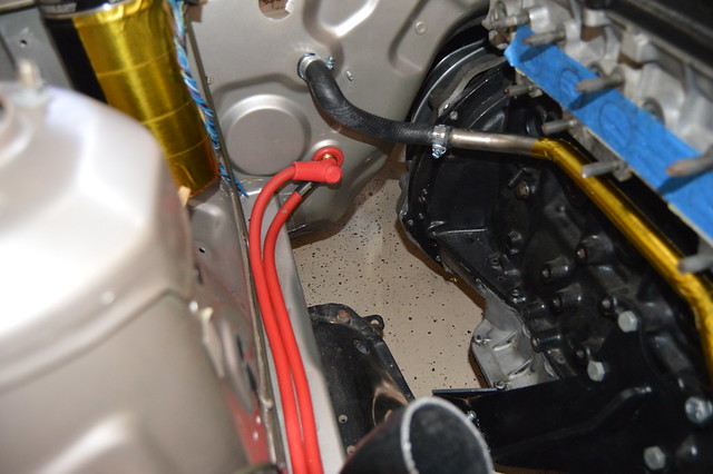
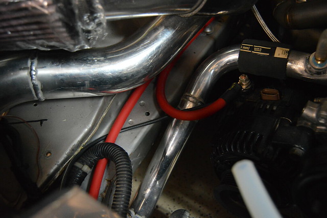
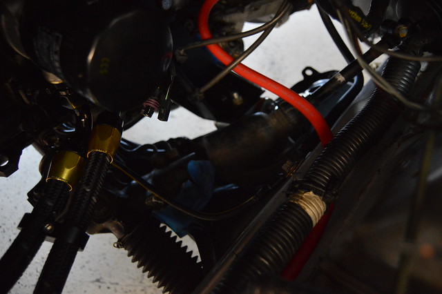
    I also cleaned up the lines for my breather setup and routed some things differently.


    I have a chasebays coolant overflow on order so ignore the line running over the rad support. I will likely mount the overflow under the air filter.


    Last edited by danny33; 04-06-2018, 09:59 PM.

    Leave a comment:


  • MikeyRa
    replied
    The carbon fiber panels on the interior a cool touch, but they just don't "fit" in my eyes.

    Excited to see this come together!

    Leave a comment:


  • Steven_318ti
    replied
    Such a build!!!

    Leave a comment:


  • gnmzl
    replied
    Just read from start the whole thread, somehow I have missed it before...
    Amazing dedication, creativity and great attention to detail make the best recipe for a build.

    Congrats on start! Sounds as good as it looks.

    Leave a comment:


  • danny33
    replied

    Leave a comment:


  • danny33
    replied
    Update time! Got in hopefully what is my last order from racespec. More splices, ring terminals, and a DTP 4 pin connector. Here is the completed engine harness which includes plug and play jumper harnesses for the mazda connector for switched 12V and the starter solenoid.
    DSC_4550 by dan reyno, on Flickr

    DSC_4547 by dan reyno, on Flickr

    this is the coil pack sub harness which includes cylinder head ground, 12V ground (grounded at block), and 12V+. I wired in a new relay using the open ABS bus bar in the OEM fuse box and triggered by a mazda keyed 12V source. Small harness is the switched 12V jumper for injectors, VVTI, IAC, and alternator


    and installed


    The other thing i was waiting on was ring terminals for the fuel pump and other assorted things. Fuel pump is now all complete and wired up. This is raychem RW-200 which is fuel cell spec heatshrink.


    Trimmed up the cubby and got the battery tie down heatshrinked since it was pretty close to my terminals.


    I powered everything up again and confirmed that i have 12V where i need it and that the starter solenoid got power (bypassed the security module).

    Used some spare hardline for a cleaner coolant line running to the swirl pot. This is the second highest point in the head other than the rear heater core outlet.


    Ordered some titanium exhuast studs from fuse fab (same guy who built my manifold) and then spent 3 hours getting this silly manifold on. basically, due to them being 12PT 13MM nuts, it was near impossible to tighten the rear bottom 2 nuts as they were making contact with the runner. I ended up using 2 nuts and the Ti washers so i could just use an open end to tighten them. Also attempted to make a tool but it didnt work out.


    Comparison of my cut studs, the OEM, and the Ti


    And finally all mounted and torqued


    Hotside all torqued to spec for hopefully the last time.


    5 months later.. finally got around to clear coating my carbon bits since it was so nice out


    How she sits now. ordered plugs and a serp belt then have to pressure test the cooling system, flush the fuel lines, fill her up with fluids, then prime the turbo. I also powered up my AEM infinity to load the latest firmware. I have a base tune being worked on by Vlad and have spoken to a local driveshaft shop about building me a steel shaft (to hold me over until i go 8.8 kit). We are getting pretty close to hearing this thing for the first time!! Once it is running without any bugs i will buy a master cylinder and clutch line so i can drive her around before registering it in TX.

    Leave a comment:


  • Snowdaze
    replied
    This is completely nuts, amazing work and detail!

    Leave a comment:


  • danny33
    replied
    Originally posted by MikeyRa View Post
    I love the dedication to quality parts and workmanship!

    We need more builds like this!
    THANK YOU! I am trying so hard to do things right the first time while learning along the way.

    Originally posted by SebastienPeek View Post
    I get super excited when I receive an email that this thread has been updated.
    Once again, the attention to detail is amazing. I am thoroughly enjoying this way too much.

    I do have a question though, and it might help others or yourself later on in the build, but is there anyway you have documented the things you've purchased and where from?

    I mean, a parts list + where to buy would be very helpful to those that don't even know where to start with this kind of wiring overhaul as well as later down the track when something needs to be replaced, you have somewhere to find out exactly where you got it from originally?
    Thanks buddy! I do keep the paper invoices for the wiring stuff and have all other order receipts in my email. As far as wiring supplies go, i use prowire and race spec (racespeconline.com) exclusively unless i need a random toyota connector or pins then i use driftmotion. Everything else in the wiring department came from those two sites as they have the best pricing. race spec is also local to where i grew up in NY so i try to support them as much as i can. But as far as a parts list, i feel its specific to each persons build and i can even improve more if/when i do it a second time. I have placed so many fucking orders between racespec/ prowire that they both probably are thinking WTF is this guy doing each time one goes through LOL. In a perfect world i'd have inventory of everything and buy spools of raychem/ tefzel and never have to wait but oh well. I probably have around $1000 into these 3 harnesses and that includes the flying lead harness, OEM connectors, all supplies, and $300-400 worth of tooling/ crimpers.

    Leave a comment:


  • SebastienPeek
    replied
    I get super excited when I receive an email that this thread has been updated.
    Once again, the attention to detail is amazing. I am thoroughly enjoying this way too much.

    I do have a question though, and it might help others or yourself later on in the build, but is there anyway you have documented the things you've purchased and where from?

    I mean, a parts list + where to buy would be very helpful to those that don't even know where to start with this kind of wiring overhaul as well as later down the track when something needs to be replaced, you have somewhere to find out exactly where you got it from originally?

    Leave a comment:


  • MikeyRa
    replied
    I love the dedication to quality parts and workmanship!

    We need more builds like this!

    Leave a comment:


  • danny33
    replied
    Originally posted by Benwalsh91 View Post
    This is mind blowing! amazing work man.
    Thanks man, appreciate it

    Lets get all caught up! The engine harness is complete after making some last minute changes due to fitment with the intake manifold. Cut off the straight boot and reorientated the harness for a 90* boot which worked out perfect. Also depinned all the injector connectors and added raychem to those circuits.


    With this mainly completed, it was time to run battery cable so i could find my switched 12V sources to fully finish up this harness and all wiring. I am using prowire usa motorsports battery cable which is very flexible and a better suited option than welding cable. 2ga used here. As i mentioned before, i am running a 2ga from the battery + to this firewall bulkhead.


    From there, i ran a 2ga to the alternator and then another 2ga to the starter. There is then a 6ga running from the alternator post to the OEM underhood fusebox


    I purchased this 10 ton hydraulic crimper (betool brand) for 40 bucks of amazon (best reviews in comparison of the others) and am very happy with it.


    And finished product-

    i have been finishing these off with DR25 when using a rubber boot or with SCL adhesive lined when running without the boot.

    Due to packaging i ended up remaking the upper power distribution panel. The 200A breaker is set between the battery + and the 2ga cable to the firewall. The interrupt switch is set between the battery + and the bussman fuse box which powers the fuel pump and ECU. I chose this method so i can hit the interrupt switch and it will power down the ECU and kill fuel. Tripping the 200A breaker only risks a voltage spike from the alternator and also the possibility of the alternator powering the fuse box without the battery.


    Backside- 6ga power cable from the interrupt switch and between the bussman posts.


    Picked up a D35 yellow top and finished up with power/ ground cables. I chose to use the rear seat seatbelt threaded hole for my ground and of course cleaned all grounds to bare metal. From the engine block to battery negative im at .04 ohms.


    Wish i didnt have to cross the cables like this but the posts were practically touching the cross bar when oriented the other way.


    Also got all my engine grounds made. I went with a 2ga running from the starter body/transmission bellhousing to frame rail and a 6ga from the block to frame rail on the starter side of the engine. On the other side, i ran a 6ga from the block to firewall and will be adding a 2ga from the alternator housing to the frame rail. I will also add another 6ga from the cylinder head to firewall.

    With that all handled i ran some temporary splices for the wideband gauge and flipped the switch


    This was a milestone for this build as i am getting so damn close to firing it up. I am placing an order this week for some more splices and ring terminals so i can finish up the ECU ground and wire my switched 12V inputs inside the cab. I will also be probing around the engine side connectors to find switched 12V for the coils, injectors, IAC/VVTI, and then wire up the fans.

    Non wiring related, i finished plumbing my heater lines


    Not sure if i added this but installed my sandwhich plate for oil pressure/temp


    ordered this rivnut tool (marson RN1) and mounted my FRP higher so i could finish my return line plumbing


    And then got my fuel line mounting/ routing finished up. I had to revise this since the fab shop welded the crossmember brackets. Much happier with this option as its isolated from the chassis. BTW found these decent billet separators on ebay. 8 pcs for $26 as opposed to $12 a piece on jegs. Drilled them out for larger hardware and used nylon bushings


    Still need to order 3 more feet of -6 and fittings for the pump hanger return line.

    Went with some PTFE -8 for the pump hanger. Hopefully i dont run into any issues using this method but after the fact i found some submersible PTFE line on radium engineerings website.


    Picked up some -10 separators as well for catchcan and oil cooler lines.


    At some point i lowered her back down a little in attempt to build motivation (it worked)


    And then spent an hour cleaning metal shavings from my intercooler pipes and coolant pipes. Not too happy about that but this is what happens when you dont do things yourself. This is how i got all the piping back and there is some sitting in my intercooler which i will have to flush. I used cut up microfiber towels and pushed them through the piping with extensions and then using water from the hose


    Scooped up some 265/40/18 NT01's as wel. Might mount these after the texas "winter" since they apparently dont like temps below freezing.


    After i get my switched 12V wired up and everything back together i will order my basetune and get some new sparkplugs. Then i can pick up fluids and order a driveshaft before i can drive her!!!!!!

    Leave a comment:


  • Benwalsh91
    replied
    This is mind blowing! amazing work man.

    Leave a comment:


  • danny33
    replied
    little update, been finishing up with wiring and had the harness complete but did not like how close the shrink boot was to the intake manifold so i cut it apart and have a 90* boot on the way. Also have some more raychem as i depinned the injector connectors to add heatshrink to those circuits. Other than that i need to connect to some switched 12V and finish up battery cable routing.

    After finishing up wrapping the engine side harness i decided it was too long for my liking after it was fully terminated so i depinned the entire connector and snipped it. second run came out much better minus the interference with the shrink boot. Already have it set at 90* and clearance/ harness slack is perfect.


    picture dump of some heatshrink added to various legs of the oem harness and new circuits


    final resistance check to verify all pins are correct. this was from ecu connector to each component connector.


    got the ignition harness completed as well. Splice work here


    and finished up with a DTP. not the cleanest work but functional and room for expansion/ modification in the future.


    And size difference between a size 12 contact and size 20.


    Need to terminate the other side and run to switched 12V, and ground.


    Finished harness which needs the 90* boot before its all done


    I read a good article on ECU grounding which led to me adding a busbar for the ECU grounds which i will ground to the engine block as opposed to battery negative.


    Have to finish up the engine harness, run some battery cable, add switched 12V inputs, then finish up plumbing my fuel return line and we can get a base tune loaded up and see what happens.

    Leave a comment:


  • SebastienPeek
    replied
    I had the exact same thought, I'm glad that you check continuity regularly!

    This is seriously awe inspiring though, the attention to detail in this build overall is amazing. Once again, wiring and engine bay pr0n.

    Leave a comment:


  • danny33
    replied
    Originally posted by loekaaz View Post
    Oh imagine the horror when you made a mistake somewhere.... That's what I'm affraid of with my project. I haven't hot wired my car before finishing the looms. So if something is interfering, I might just have a lot of un-wiring to do...
    i check continuity between each pin 2 times on different days just to make sure i have it right lol. will be doing that again from the ECU connector to each toyota connector as well before gluing on the heatshrink boot

    Leave a comment:

Working...
X