 Tweet
Tweet
Today, we move towards the conclusion of the installation of the Bagyard Bombers/AccuAir airbag setup on this B6 Audi A4.
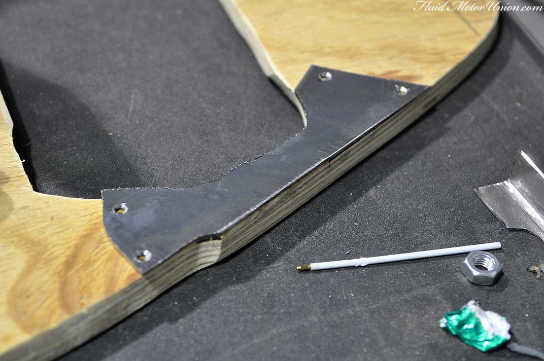
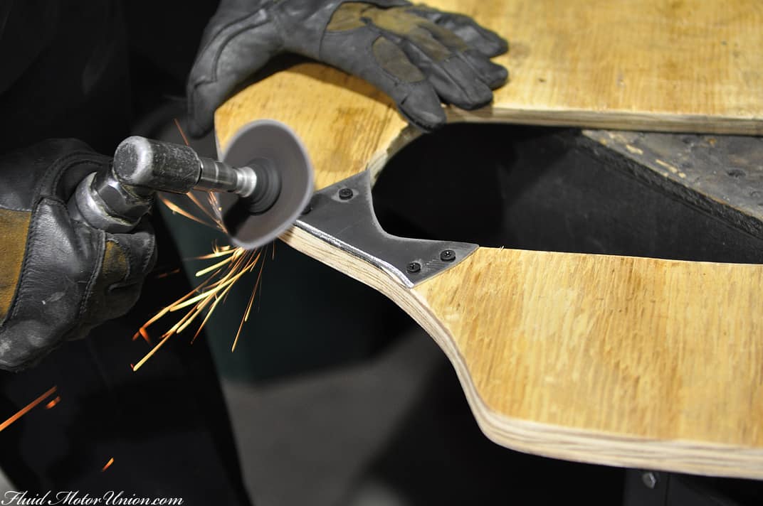
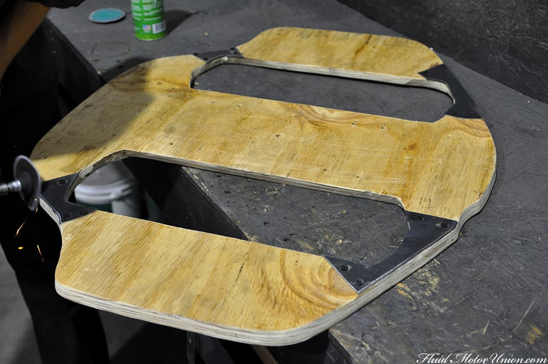
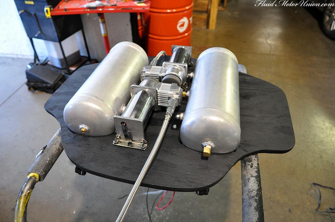
We�ll start with the same part we ended with last time � the new wood floor that will be holding the tanks and compressors in place over the electronics underneath. As we had to keep lifting the tanks and compressors in and out of the car during fitment, we found one issue with the wood floor that could spell disaster. Namely, it all had to do with those skinny corners of the floor; those four areas provide a wonderfully small amount of weight bracing, and could potentially break when lifting up the whole floor assembly. Seeing as how we didn�t want splinters flying everywhere (with either us or the owner removing it), we set about making some reinforcements. A few quick cuts on a steel plate, followed by a good bit of grinding to get its shape in place and some wood screws to top it off, and we had ourselves one reinforced wood floor.
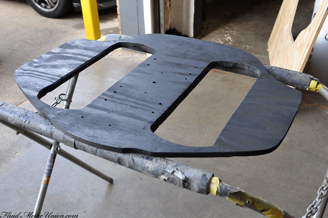
After the reinforcements were added, we painted the whole floor black. Now, the only thing that will pop in the trunk will be the compressors and the tank, as the wood floor will now melt into darkness with the rest of the surrounding trunk space. After all, while we like the floor we made, by no means is it the centerpiece to the airbag installation.
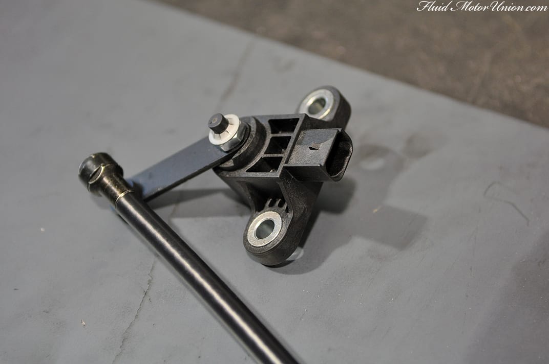
With the floor and all the trunk-to-underbody wiring (electronics and air lines) finished, it�s time to tackle the last piece of the puzzle � the level sensors. They�re relatively small, requiring only two bolts to hold them in place. Extending from the sensors are long bars, meant to connect to a piece on the suspension that moves up and down with ride height (lower control arms are usually a popular piece to connect them to). This way, he�ll be able to have his presets in the AccuAir E-Level system that will allow him to quickly jump to speedbump-ready mode without having to squint at a gauge and remember what height is correct.
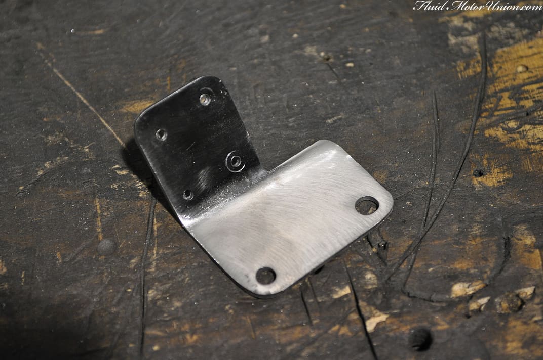
We had originally handcrafted some neat little brackets to provide for a more professional-looking install with a more directly up-and-down movement to the sensors� arms. Sadly, the angle of the brackets moved the sensors just a little too close to the wheel for our personal tastes (and we don�t want any issues with parts improperly touching one another), so we ditched them. But they turned out nice, so we decided to put them here on the blog anyway.
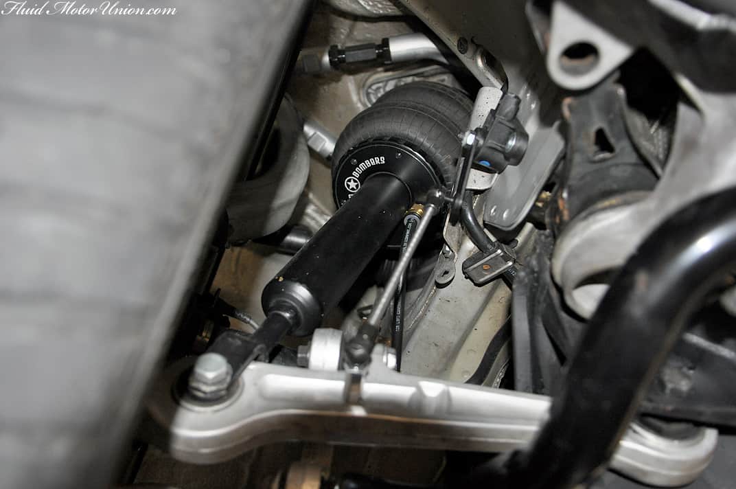
There wasn�t much room in the front wheel wells for pictures of the installation. That being said, there wasn�t a whole lot of room available in the wheel well to shoot the parts once they�d gone on, either. Taking that into account, we did shoot one picture of each front strut assembly with the sensors in place on the body, they�re just lit using the awful, awful built-in flash on the Nikon. So it goes.
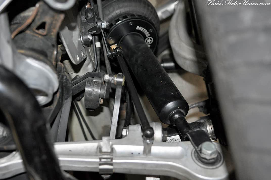
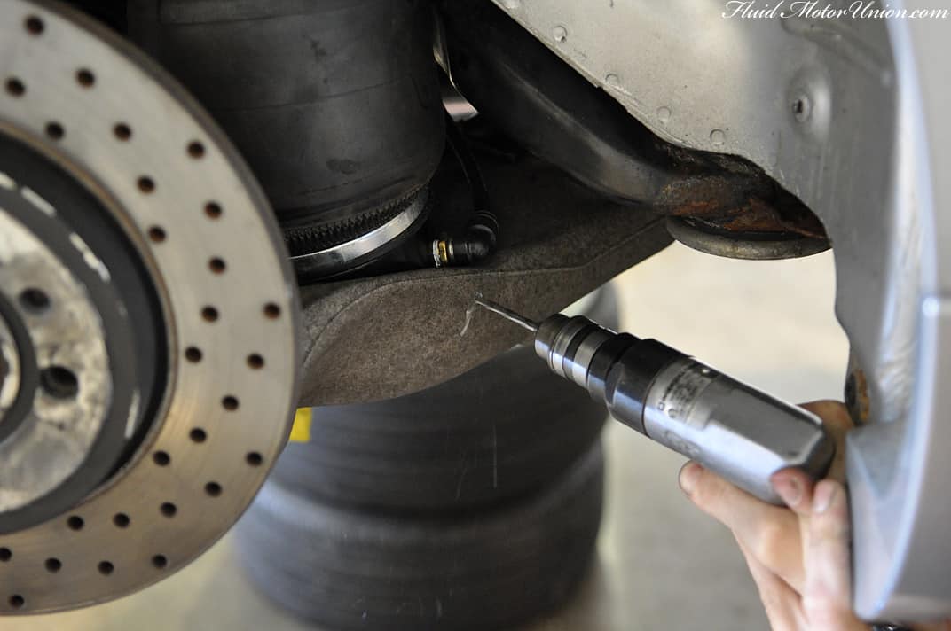
The rears, however, had a greater amount of free space for plenty of photography, so we�ll give you a quick rundown on how to install the level sensors out back. The first point consists of finding a solid mounting point for the level sensor. You want it to be as flat as possible, so the bolts will mount up flush with the body. You also want to be able to get to the back of the mounting point, as there�s going to be a nut back there used to hold the sensor�s bolt in place. It also needs to be away from moving parts, within reach of the sensor�s harness and close enough for the sensor�s arm to make it to its own mounting point. Taking all that into account, we found a spot just in front of the shock; there�s even a little plug that we can pull to access the back of the body. Lovely.

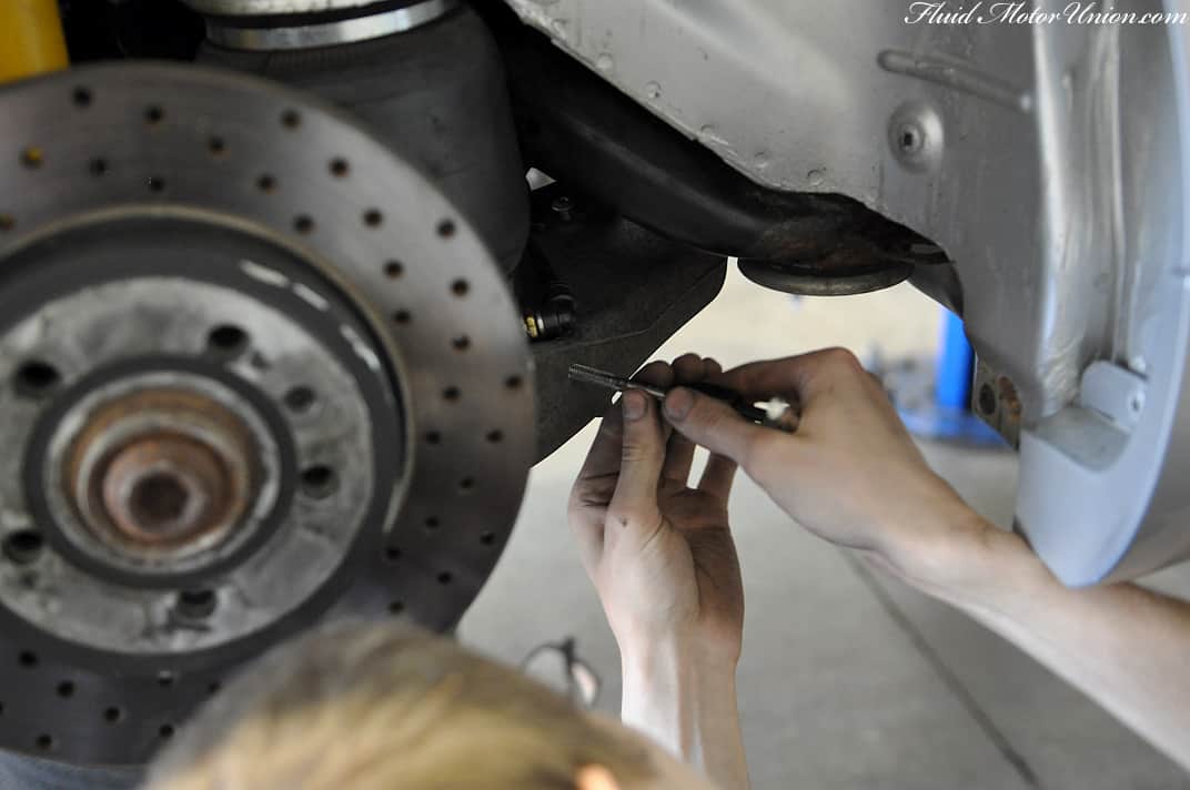
After tightening your sensor down, it�s time to drill the hole for the level sensor�s arm. It, too, just like the sensor, needs to have a hole drilled for its mounting point. Given the length of the arm and the required area in which it travels, we utilized the lower control arm for this purpose. It doesn�t matter if both sides aren�t exactly even with each other across the body; there�s a calibration step later on to set the �normal� angles for the sensor. A drill with a slowly increasing size of bit will be needed for this step. It helps to start with a punch, then a smaller gauge bit, eventually moving up to the full-sized ones. Once that�s drilled out, the arm needs to be screwed into the control arm, so you�ll need to get out your threader and make the appropriate threads inside the hole.
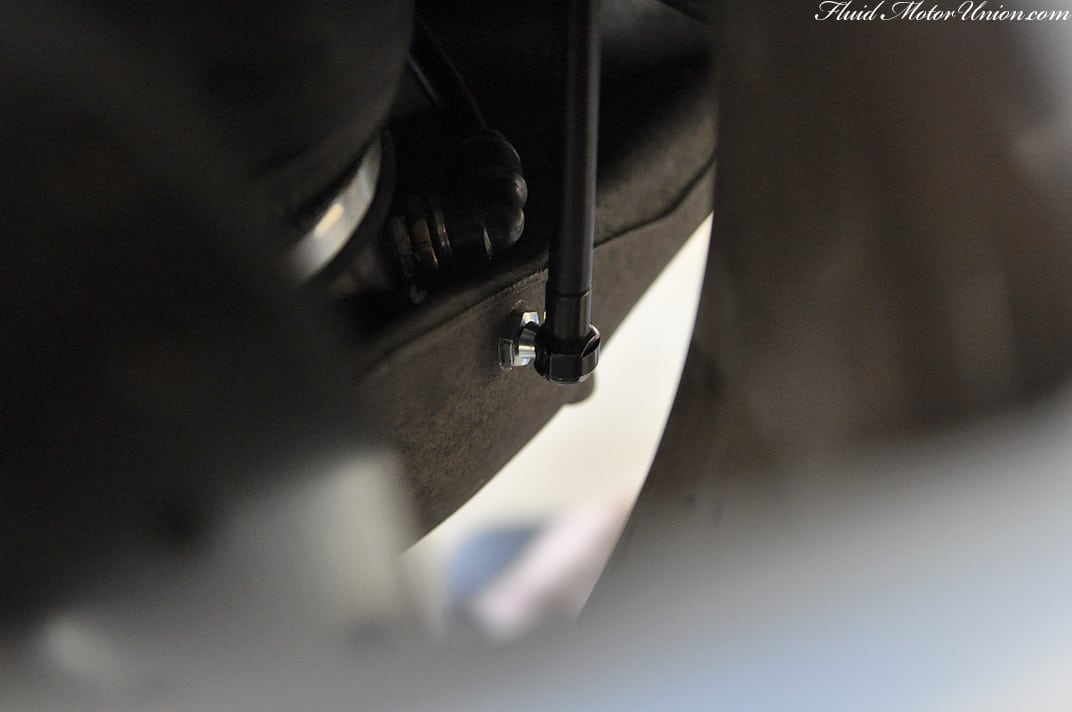
And then you tighten everything down and that�s all she wrote. With our parts in place, it takes a bit more than a quick eye to notice that there�s an extra piece hanging out behind the wheel. Unless you�re an Audi or airbag aficionado, you probably won�t even notice they�re there.
At this point, you might be asking, �Well, how low does it get?� Low. It gets low. And bear in mind, this is without frame notching or any sort of work done to the wheel wells. So, in theory, it can get even lower.

We�ll have final pictures and all that once everything is neatened and tidied up. For now, though, it�s time to sweat the small stuff in the build while we wrap it up. See you all tomorrow!
We�ll start with the same part we ended with last time � the new wood floor that will be holding the tanks and compressors in place over the electronics underneath. As we had to keep lifting the tanks and compressors in and out of the car during fitment, we found one issue with the wood floor that could spell disaster. Namely, it all had to do with those skinny corners of the floor; those four areas provide a wonderfully small amount of weight bracing, and could potentially break when lifting up the whole floor assembly. Seeing as how we didn�t want splinters flying everywhere (with either us or the owner removing it), we set about making some reinforcements. A few quick cuts on a steel plate, followed by a good bit of grinding to get its shape in place and some wood screws to top it off, and we had ourselves one reinforced wood floor.
After the reinforcements were added, we painted the whole floor black. Now, the only thing that will pop in the trunk will be the compressors and the tank, as the wood floor will now melt into darkness with the rest of the surrounding trunk space. After all, while we like the floor we made, by no means is it the centerpiece to the airbag installation.
With the floor and all the trunk-to-underbody wiring (electronics and air lines) finished, it�s time to tackle the last piece of the puzzle � the level sensors. They�re relatively small, requiring only two bolts to hold them in place. Extending from the sensors are long bars, meant to connect to a piece on the suspension that moves up and down with ride height (lower control arms are usually a popular piece to connect them to). This way, he�ll be able to have his presets in the AccuAir E-Level system that will allow him to quickly jump to speedbump-ready mode without having to squint at a gauge and remember what height is correct.
We had originally handcrafted some neat little brackets to provide for a more professional-looking install with a more directly up-and-down movement to the sensors� arms. Sadly, the angle of the brackets moved the sensors just a little too close to the wheel for our personal tastes (and we don�t want any issues with parts improperly touching one another), so we ditched them. But they turned out nice, so we decided to put them here on the blog anyway.
There wasn�t much room in the front wheel wells for pictures of the installation. That being said, there wasn�t a whole lot of room available in the wheel well to shoot the parts once they�d gone on, either. Taking that into account, we did shoot one picture of each front strut assembly with the sensors in place on the body, they�re just lit using the awful, awful built-in flash on the Nikon. So it goes.
The rears, however, had a greater amount of free space for plenty of photography, so we�ll give you a quick rundown on how to install the level sensors out back. The first point consists of finding a solid mounting point for the level sensor. You want it to be as flat as possible, so the bolts will mount up flush with the body. You also want to be able to get to the back of the mounting point, as there�s going to be a nut back there used to hold the sensor�s bolt in place. It also needs to be away from moving parts, within reach of the sensor�s harness and close enough for the sensor�s arm to make it to its own mounting point. Taking all that into account, we found a spot just in front of the shock; there�s even a little plug that we can pull to access the back of the body. Lovely.
After tightening your sensor down, it�s time to drill the hole for the level sensor�s arm. It, too, just like the sensor, needs to have a hole drilled for its mounting point. Given the length of the arm and the required area in which it travels, we utilized the lower control arm for this purpose. It doesn�t matter if both sides aren�t exactly even with each other across the body; there�s a calibration step later on to set the �normal� angles for the sensor. A drill with a slowly increasing size of bit will be needed for this step. It helps to start with a punch, then a smaller gauge bit, eventually moving up to the full-sized ones. Once that�s drilled out, the arm needs to be screwed into the control arm, so you�ll need to get out your threader and make the appropriate threads inside the hole.
And then you tighten everything down and that�s all she wrote. With our parts in place, it takes a bit more than a quick eye to notice that there�s an extra piece hanging out behind the wheel. Unless you�re an Audi or airbag aficionado, you probably won�t even notice they�re there.
At this point, you might be asking, �Well, how low does it get?� Low. It gets low. And bear in mind, this is without frame notching or any sort of work done to the wheel wells. So, in theory, it can get even lower.
We�ll have final pictures and all that once everything is neatened and tidied up. For now, though, it�s time to sweat the small stuff in the build while we wrap it up. See you all tomorrow!


