Announcement

Collapse
No announcement yet.

Widebody Hardbody

Collapse
X
 
  • Filter
  • Time
  • Show
Clear All
new posts

  • #16
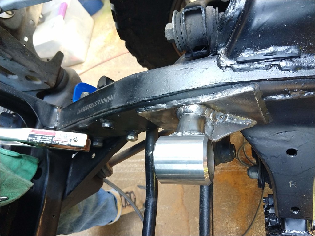
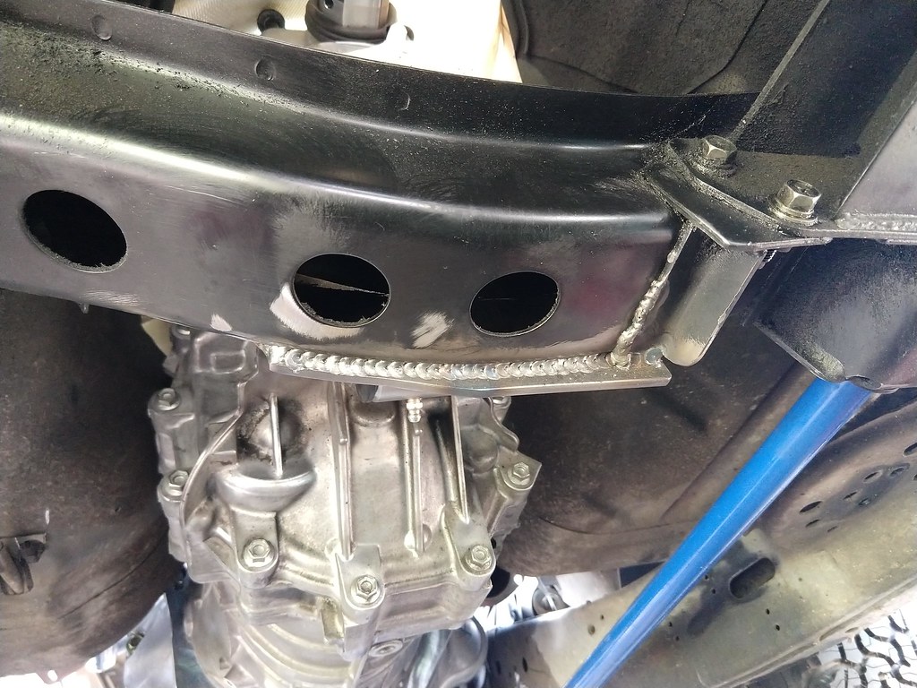
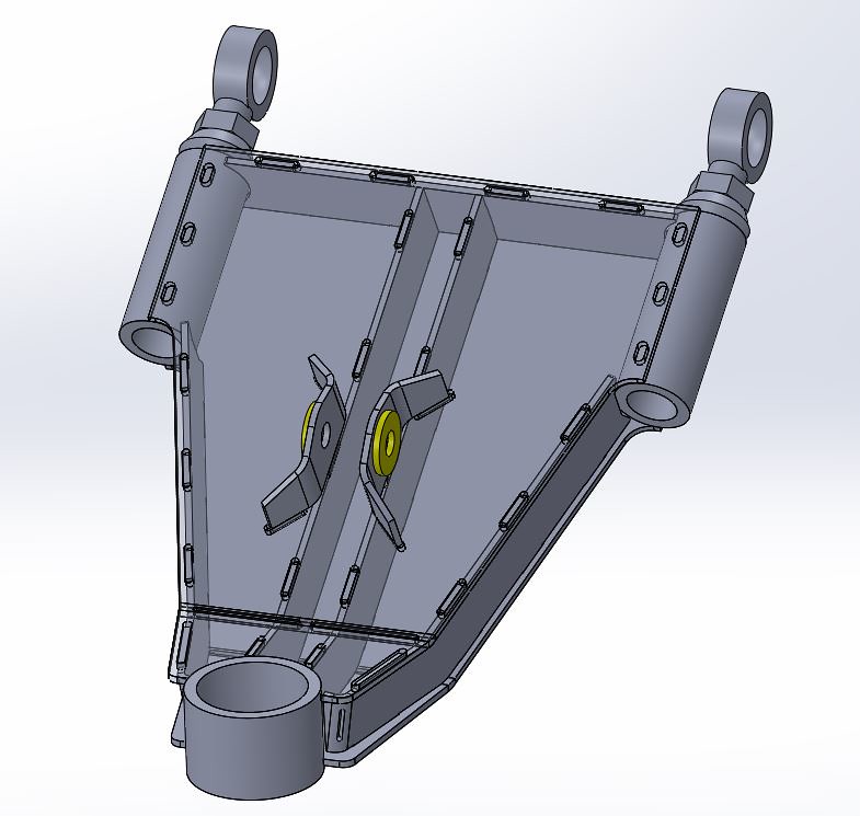
    Engine mounts and transmission mount are finished.
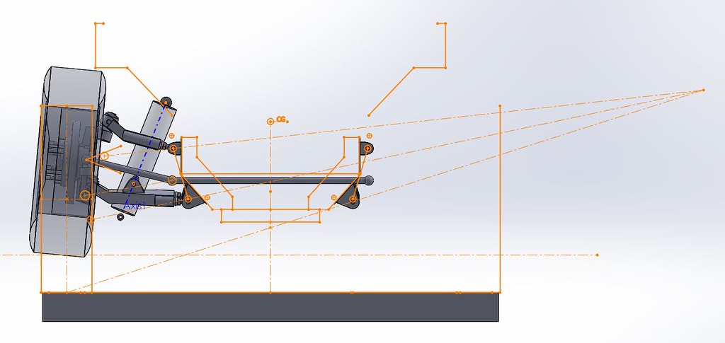
    IMG_20200712_152210499

    Driver:
    IMG_20200712_152242759

    Passenger:
    IMG_20200712_152236459

    Trans:
    IMG_20200712_125553194

    IMG_20200712_125609783

    IMG_20200712_150202096_HDR

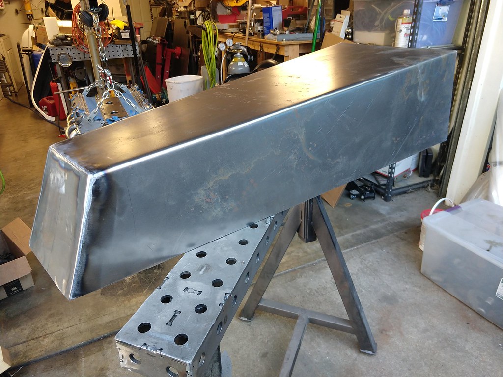
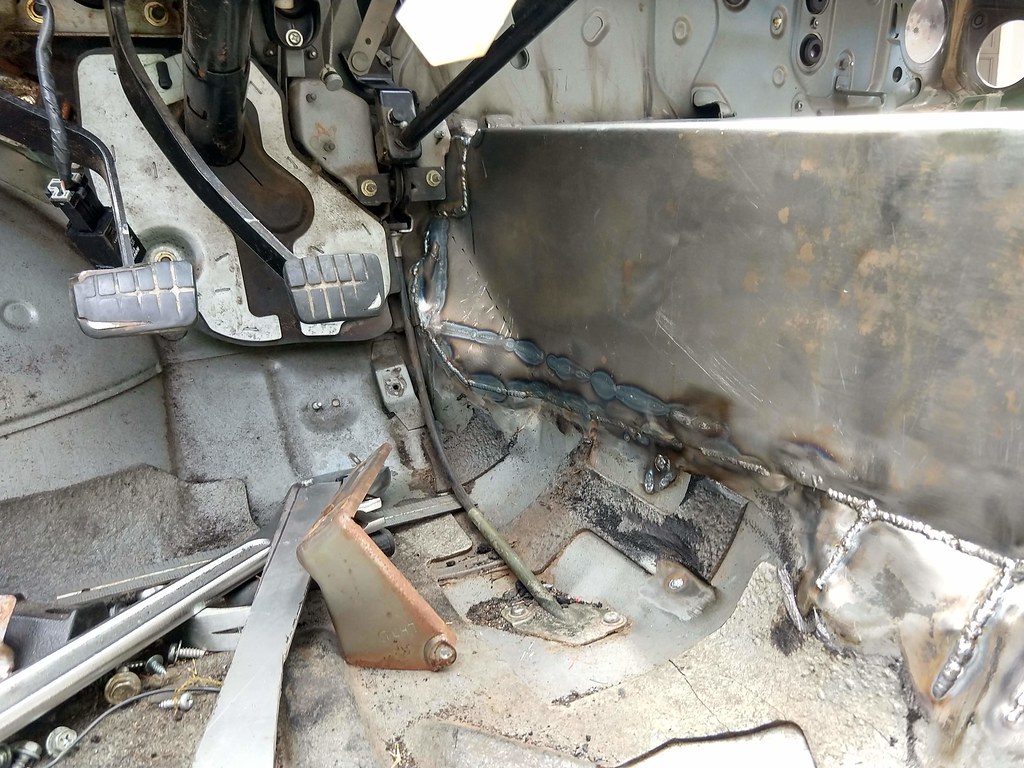
    And I've started mocking up the new transmission tunnel. I'll also be mounting the hydro hand brake to this, and hopefully adding a couple cup holders. I think I'll go one inch narrower in the rear of the tunnel than this mock-up. Also keep in mind it needs to slide slightly further forward than pictured but I have to dig more insulation off the firewall piece by piece till I can get it in there.
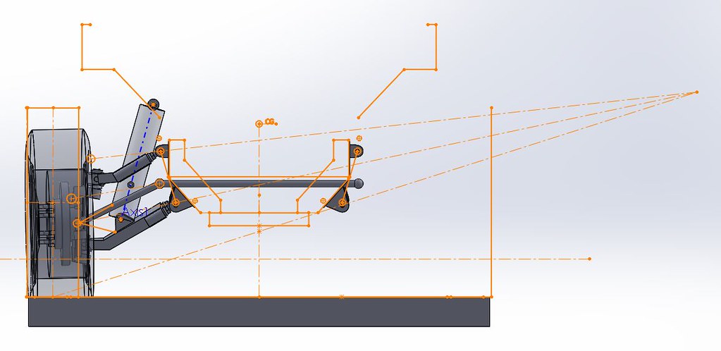
    IMG_20200712_192146665

    IMG_20200712_194321045_HDR

    IMG_20200712_194448183

    IMG_20200712_194453964

    Comment


    • #17
      this thing is fucking rad!

      Instagram: @half_lung

      Comment


      • #18
        Originally posted by scweet14 View Post
        this thing is fucking rad!
        Thanks!

        Comment


        • #19
          Over the last couple weeks, I've gotten the trans tunnel cut out of 16 gauge, and folded it up on a finger brake at work. I ended up making the end cap a separate piece, and also altered the design versus the cardboard mock-up. It's now the same width at the base, but tapers to an inch narrower at the top.

          IMG_20200713_190842999_HDR

          IMG_20200714_094906005

          End cap welded on and ground smooth.

          IMG_20200714_184305058

          Then came the arduous task of getting it to fit the floor and firewall. I had to totally strip everything off the dash to get enough access to the firewall, then spent about two and a half days trimming and heating and beating to get everything to meet up properly. It's fully seam welded along the entire perimeter inside the cab.

          IMG_20200719_150014921_HDR

          IMG_20200719_142945240_HDR

          It was then etch primed.

          IMG_20200719_155604025_HDR

          And I gooped up the underside with seam sealer.

          IMG_20200721_081300107

          Finally the fan, heater core, and AC evaporator went back in. I had to remove everything that allowed air to be directed at my feet, but that's no big deal.

          IMG_20200721_201757547

          And now for some big changes, I've been designing my own front suspension. I'm starting with the knuckles from a 2012 2WD Silverado, so that the stud pattern matches the Tahoe rear axle. Also they're cheap, and not super tall like a Tacoma knuckle, and they're front steer which is important for engine clearance. The knuckles have been modified to use a 1" Uni-ball joint instead of the standard ball joint. Note in the below pictures I have it mocked up with a Heim joint, which isn't what I'm going to be using in the final design.

          IMG_20200309_181823687

          IMG_20200309_150932754

          This will be a double A-arm design, which is currently designed to have 40% anti-dive, and an instantaneous roll center about 30% of the way up to the CG. These are subject to change because I'm making some educated guess about where the CG is. I'm also planning on moving the front wheels about 2" further forward, this will get me some more traction on the rear wheels, and also give me more tire clearance to the foot-well. Up front I only have to worry about running into a fiberglass fender and a bumper I haven't made yet.

          side view sketch

          front suspension view 1

          I've designed it to have about 6 inches of bump and 4 inches of droop. Bump steer going up is pretty good, as it sags down I get like a half degree of toe-in.

          front suspension view full bump

          front suspension view full droop

          This would be with a 6.5" stroke shock and a 500-550 lb/in spring, which results in around a 1.6 hz natural frequency. Again, these numbers will change a bit once I get the truck on some wheel scales and get true numbers for sprung and un-sprung weight.

          And here's a shot of the basic design of the A-arms. These will be cnc plasma cut 10 guage plates that will tab and slot together to self jig into the right shape. Those inboard plates that the A-arms connect to is designed to be welded to the outside of the frame rails so I can actually position the arms correctly in space. You can also see what the uni-ball joints look like.

          front suspension view 2

          front suspension view 3

          Comment


          • #20
            Spent the weekend turning the A-Arms into a real sheet metal design that tab and slots together. This is primarily 10 gauge cold rolled sheet, with the threaded bungs for the heims being welded into 1.5" OD, 0.25" wall DOM tubing.

            The upper arm should be right at 10 pounds for the weldment, plus a little bit more for the uniball bearing and the ball of the heim joints. Upper arm design:

            outer view

            Exploded view:

            Exploded View

            The lower arm is right around 15 pounds. Lower arm:

            top view

            Exploded:

            exploded view

            And I also ran a little FEA simulation on a simplified model of the lower arm. The test shown here is at 2000 pounds force at the shock mount, but peak force at end of travel will be something close to 3200 pounds.

            displacement view

            And here's both arms together:

            Both arms

            And I played around a little bit with nesting the parts for cutting. Basically an upper lower pair worth of parts fits on a 48x16 sheet.

            Nested A Arms

            I sent these drawings off to a laser cutter yesterday, and hopefully I'll have parts next week sometime.

            Comment

            Working...
            X